1.0 PURPOSE
2.0 SCOPE
3.0 APPLICABLE DOCUMENTS
4.0 RESPONSIBILITY
5.0 MANPOWER
6.0 TOOLS & EQUIPMENT
7.0 METHODS/PROCEDURE
8.0 QUALITY CONTROL
9.0 SAFETY PRECAUTION
10.0 ATTACHMENTS.
INSTALLATION OF CATALYST LIFT LINE | METHOD STATEMENT
1.0 PURPOSE
1.0 This method statement shall provide minimum guidelines to carry out the installation of catalyst lift line in Plants and refinery projects.
2.0 SCOPE
2.0 This Method Statement covers the procedure of installation of catalyst lift line in Plants and refinery projects.
3.0 APPLICABLE DOCUMENTS
3.1 Project Specifications and Standards
3.1.1 ASME 31.3 Process Piping
3.1.2 SAES-L-105 Piping Material Specifications
3.1.3 SAES-L-310 Design of Plant Piping
3.1.4 SAES-L-350 Construction of Plant Piping
3.1.5 SAES-W-011 Welding Requirements for on Plot Piping
3.1.6 Schedule “Q” Quality Requirement
3.2 Applicable SATIP/SAIC/SATR
3.2.1 SATIP-L-350-01 SATIP for On-Plot Piping Installation.
3.2.2 SAIC-L-2005 Recv Inspection of Pipe and Pipe Nipples (Plant Piping).
3.2.3 SAIC-L-2017 Piping/Equipment Internal cleaning inspection.
3.2.4 SAIC-L-2035 Cutting & Assembly Fit-Up.
3.2.5 SAIC-W-2005 Pre-Welding Inspection (Shop & Field) of Plant Piping.
3.2.6 SAIC-W-2006 In-process welding inspection.
3.2.7 SATR-A-2007 Pre-test Punch List Form .
3.3 Standard Drawing/Latest Revision Documents
3.3.1 Catalyst lift line equipment drawing
3.3.2 Catalyst circulation lines specification J10-L-DAT-VB-554235
4.0 RESPONSIBILITY
4.1 Construction Manager is responsible for implementing HSE and shall study, analyze and schedule all construction activities with his department to include manpower and equipment line up as well as other possible resources required for the successful implementation of the construction work activities. Study all aspects of work procedure as per JV Technical Scope of Work.
4.2 Piping Superintendent shall assist Construction Manager in the overall construction activities. Receives and carries out directives and strategies of Construction Manager in various phases of duties assigned by this immediate Supervisor.
4.3 Piping Supervisor shall be directly reporting to the Piping Superintendent and responsible for the implementation and control of all site activities per Technical Scope of Work and latest approved construction drawings. He shall coordinate with other discipline to visualize possible conflicts in the drawing as well as in the schedules to provide other options in preventing unnecessary delays and obstructions.
4.4 Material Control Manager has the responsibility to:
4.4.1 Receiving and maintaining of material
4.4.2 Control of material stock status before release to construction team.
4.4.3 Issuance of material to piping construction.
4.4.4 Request the material receiving inspection to QA/QC team.
4.5 The Welding Supervisor and/or Foreman are solely responsible to ensure that all welding works are in conformance with applicable codes, standards, specifications and approved procedures.
4.6 Piping Foreman shall be responsible for the direct work supervision at site and ensure that the work is performed in accordance with JV Technical Scope of Work and latest approved for construction drawings. He shall monitor the availability of materials in line with his required schedule.
4.7 QC Inspector shall be responsible in monitoring and inspection of the work and ensured that the work is performed and properly documented in accordance with project requirements
4.8 Safety Supervisor shall be responsible in monitoring safety aspects and ensuring that the work is done in accordance with JV Safety Standard Procedure. He shall discuss to the workers the characteristics of related materials and status of work area giving reminders as an additional point to injury and incident free environment.
5.0 MANPOWER
5.1 The Piping Supervisor shall control the overall activity of installation of catalyst line and he shall be directly reporting to the Piping Superintendent/Construction Manager. The basic manpower under him shall consist but not limited to the following:
5.1.1 Piping Foreman
5.1.2 Welding Foreman
5.1.3 Pipefitters
5.1.4 Welder
5.1.5 Crane Operator (Aramco Certified)
5.1.6 Rigger (Aramco Certified)
5.1. 7 Trailer truck Driver
5.1.8 Helper
5.1.9 Painter (by others)
5.2 QC Inspector
5.3 Safety Supervisor
5.3.1 Safety Officer
6.0 TOOLS AND EQUIPMENT
6.1 Tools and equipment needed should be in good condition and must be checked by Piping/Welding Supervisor & Safety Officer prior to use in the construction area.
These includes but not limited to:
6.1.1 Tools, Jigs Instrument
6.1.1.1 Wrenches
6.1.1.2 Magnetic/spirit level
6.1.1.3 Chain Block
6.1.1.4 Chain Puller
6.1.1.5 Bevel gauge
6.1.1.6 T-square
6.1.1.7 Straight edge
6.1.1.8 A-Frames
6.1.1.9 Tripod
6.1.1.10Gap Gauge
6.1.1.11 Hi-Lo Gauge
6.1.2 Equipment
6.1.2.1 Crane
6.1.2.2 4” Angle grinder
6.1.2.3 Pencil grinder
6.1.2.4 Cutting outfit
6.1.2.5 Boom truck
6.1.2.6 Cut-off wheel
6.1.2.7 Radial cutter
6.1.2.8 Generator set
6.1.2.9 Trailer truck
6.1.2.10 Welding Machine
7.0 METHODS/ PROCEDURE:
7.1 Preparatory Works
7.1.2 Secure work permit from DEC/JGC concerned personnel prior to start of work/activity
7.1.3 Install scaffold as required (by others)
7.1.4 Prepare all materials needed for the job.
7.2 Material Delivery and Requirement
7.2.2 Based on priority, DEC/JGC shall make the materials available for withdrawal by ARCC at least 30 days before fabrication.
7.2.1 Material shall be stored separately by its type and specification and it shall be marked according to its designed color.
7.2.2 Materials shall be maintained to comply with any warranty conditions imposed by the manufacturer.
7.3 Material Receipt, Storage and handling
7.3.1 Pipe stored outdoor shall be provided with dunnage or proper material underneath so as to avoid direct contact with soil/asphalt flooring.
7.3.2 End bevel protectors remain on pipes and fittings while in storage and protectors do not cause damage to internal or external coating (SAES-L-450 Section 8.4).
7.3.3 Slings for lifting pipe shall be nylon or similar material to prevent damage to the pipe surface. Wire rope slings shall not be used.
7.3.4 Pipe shall not be rolled or dropped off trucks.
7.3.5 Use of water repellant materials such as plastic sheet or blue sheet shall be use in covering stainless steel materials (raw materials or finished product) for protection against exposure to rain especially on outdoor Raw material lay down yard and/or on Finished Product Lay down yard.
7.3.6 ARCC QC inspector shall verify that material received conform to the applicable requirements. All the material shall be stored in safe/secure area accessible to the ARCC/JV or Company Representative.
7.3. 7 During loading and unloading of material, Certified Crane Operators are to engage for the safety operation.
7.3.8 All materials shall be stored in a planned manner for easy identification of materials and issue.
7.3.9 Materials upon receipt shall be checked for quantity by Warehouse personnel. QC Inspector to conduct material receiving inspection as per SATIP.
7.3.1 0When a length of pipe is cut from a longer joint of pipe, all vendor markings and other identifying information shall be transferred to each length of pipe.
7.3.11 Make sure that raw material are properly marked & recorded with its applicable identification marked and code numbers as per project requirements.
7.4 Installation Procedure
7.4.1 Catalyst Circulation Line Flanges
7.4.1.1 Weld joints RTJ flange and catalyst transfer pipes shall be welded at site after vessel is installed in position. Smooth surface inside of flange neck welding shall be complied. The flange inner side welding and edges must be accessible for inspection prior to flanges bolting.
7.4.2 Catalyst Circulation Line Coupling
7.4.2.1 The following procedure was selected in order to allow inside smooth weld grinding while taking care of the geometry difference (tolerances) existing between two pipes, even though the diameter and schedules are the same.
7.4.2.2 The two types of joints are described below, coupling type A and B, depending on which type is applicable on each joint. It is also advisable to provide unique numbering on all pipe ends, coupling types and welds (including the two flange welds at each end of the line) for ease of follow up and inspection.
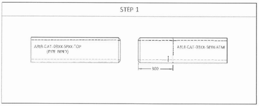
7.4.2.2.1 Coupling type A (for pipe bend joint)

1. Prepare the pipe ends for butt weld. Identify properly the pipe ends with marking at 300
mm from future weld, for example:
A313-CAT-03XX-SPXX-TOP (PIPE BEND) and A313-CAT-0305-SPXX-BTM
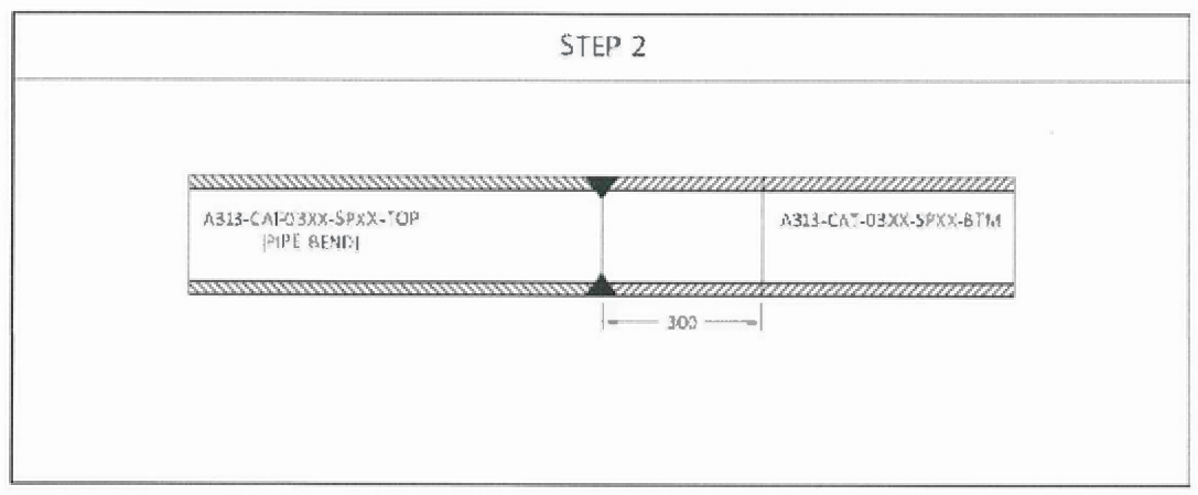
2. Weld the pipes together.

3.
Mark a line 300
mm on the pipe to be cut. Three (3) lines shall be marked with equal
distance around.

4. Cut the pipe from the weld joint in reference to spool drawing. The required length is the
distance from weld joint to the location of pipe sleeve.

5.
Machine both pipe ends perpendicularly to the inner surface axis with a maximum
tolerance of 0.05 mm.

6.
Grind the weld penetration flush at the pipe inner surface. Check for smoothness of
welding inside the pipe after grinding (for example, welding rod shall be able to slide on
the weld in catalyst circulation direction)].

7.
Insert the sleeve on the Pipe side first. Then, align the piping in reference to the marked
line. Use three (3] stiffeners connecting on both pipes to ensure that both faces are
equally touching to each other.
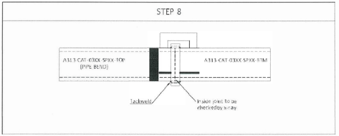
8. After ensuring ooth pipe faces are align and matching, move row the pipe sleeve to the
center of joint. Do tack weld first to ensure that radial gap is equal around the pipe before
weld. Conduct x-ray on the joint. The maximum allowable deviation is 0.1 mm.

9. Upon the radial gap was accepted by contractor QC and AXENS, fillet weld can be
carried out. Remove the stiffeners after fillet weld of two pipes. Grind the excess
flush and check for smoothness.
7.4.3 Coupling Type B (for adjustment of pipe length).
1 Prepare the pipe ends for butt welds. Identify properly the pipe ends with marking at 300
mm from future weld, for example;
A313-CAT-03XX-SPXX-TOP ( PIPE BEND) and A313-CAT-0305-SPXX-BTM

2
a 300 mm
Prepare
spool piece the same specification as the original catalyst pipe. Mark a
line through all the length of spool piece. Three (3) lines shall be marked with equal
distance around.

3
Cut the spool piece in two parts with one side equals to required length on spool drawing.
The required length is the distance from weld joint to the location of pipe sleeve. Identify
the two’parts by a marker, TOP and BTM,

4 Machine both pipe ends perpendicularly to the inner surface axis with a maximum
tolerance of 0.05 mm.
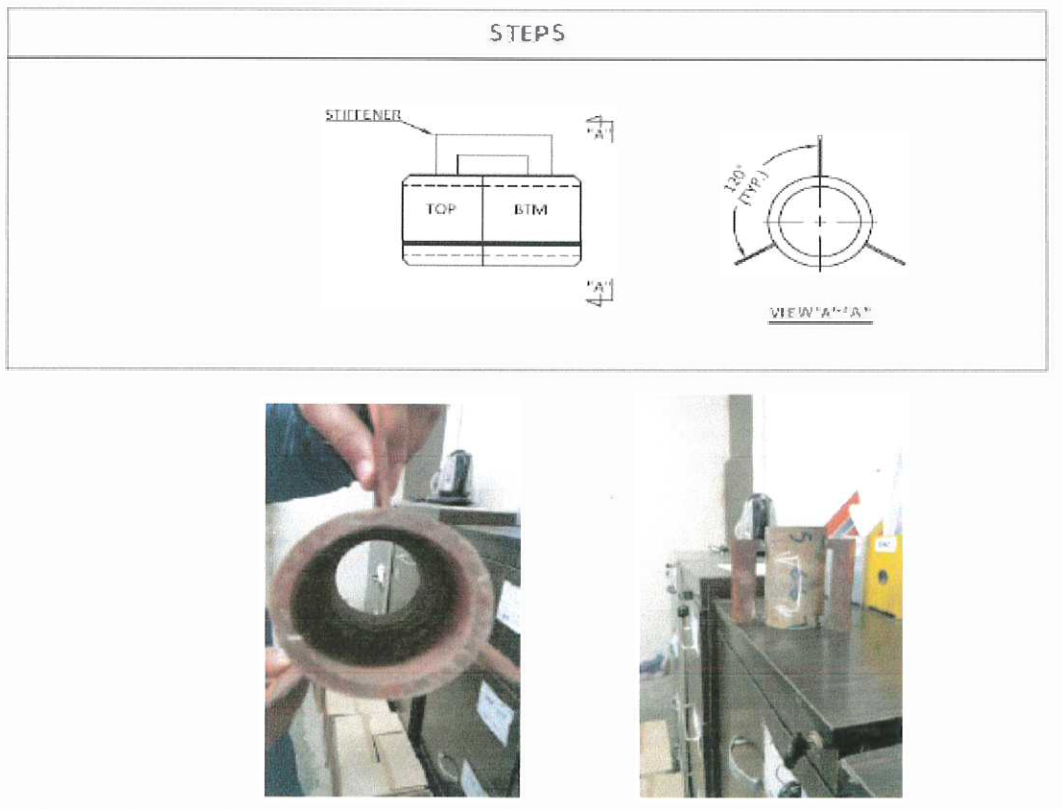
5. Align the piping in reference to the marked line. Use three (3) stiffeners
connecting on both pipes to ensure that both faces are equally touching to each
other. See photos sample.

6 Weld the joint spool piece to each pipe.

7 Remove the stiffener temporarily to allow grinding of weld penetration flush at the pipe inner surface. Check for smoothness of welding inside the pipe after grinding (for example, welding rod shall be ale to slide on the weld in catalyst circulation direction).

8 Insert the sleeve on the 3TM side first. Then, align the piping in reference to the marked line. Use the stiffeners again in connecting both parts same as step 6.

9 After ensuring both part faces are align and matching, move now the pipe sleeve to the center of joint. Do tack welding first to ensure that radial gap is equal around the pipe before weld. Conduct x-ray on the joint. The maximum allowable deviation is 0.1 mm.
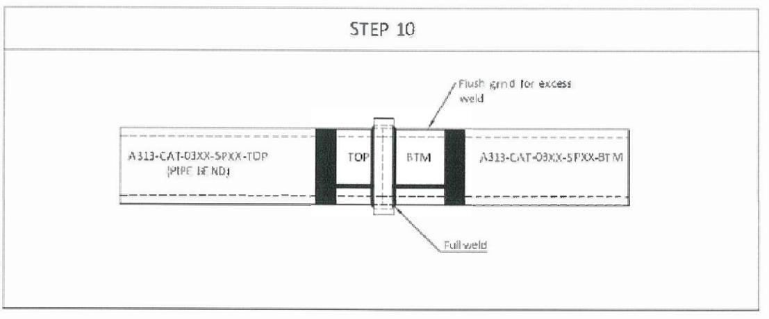
10. Upon the radial gap was accepted by contractor QC and AXENS, fillet weld can be carried out. Remove the stiffeners after fillet weld of two pipes. Grind the excess flush and check for smoothness.
7.4.4 Make RT Result for Assessment
7.4.4.1 In order to ease RT checking, it is recommended to prepare 3 pipes/sleeve installation samples with calibrated clearance between pipes, 0.1, 0.2 and 0.5 mm. These 3 samples will help to assess RT checking of catalyst pipes connection. RT can also be taken after tack weld sleeve coupling for these samples to help assessment.
7.4.5 Mock-up Test.
7.4.5.1 The purpose of this test is to verify if any possible defects may occur, such as cracks or misalignment, after heat treatment on pipe sleeve joints, and to provide necessary actions.
7.5 Touch-up painting
7.5.1 Touch-up paint of pipes spools shall be according to painting specification and procedure.
8.0 QUALITY CONTROL
8.1 QC Inspector shall be assigned to ensure the quality control and assurance requirements of the project.
8.2 QC Inspector shall be responsible to conduct all required inspection/documentation and to assure that all applicable requirements, codes and standards are complied with.
8.3 Contractor has to utilize the applicable SAIC for every activity.
9.0 SAFETY PRECAUTION
9.1 Construction Manager/Supt./Supv./FM shall be responsible for the implementation of this procedure and the required orientation necessary for the work force.
9.2 All rigging equipment shall be in good condition and possess a valid certification from authorized certifying and inspection departments.
9.3 Safety Supervisor shall monitor compliance of the entire working crew to safety procedures until the work is fully completed.
9.4 The necessary manpower inclusive of supervisory staff, tools, equipment, materials, and other resources required must be made available and ready to use.
9.5 During the activity, closely supervision shall be done by field foreman.
9.6 All workers shall wear as a minimum PPE required below:
-
- Safety Helmet
- Safety glasses
- Safety Shoes
- Gloves
- Mask, if required to prevent inhalation of dust and welding gas 9.6.6 Ear plug, if required by conditions.
- Machinery like grinding wheel cutter shall have a protection method.
- Safety shall be requested and carried out in accordance with safety procedure.
9.7 All necessary personal protective equipment (PPE) shall be provided and to be worn at all times in accordance with site Safety Procedure.
9.8 Sufficient lightings shall be provided if work is done at night time. Work at night shall be approved by client.
9.7 Good housekeeping must be maintained in the duration of works.
9.8 The area shall blocked by physical barricade or warning tapes during activities is to be done to ensure safety.
9.8 Job Hazard and Risk Assessment (JHRA) of this method statement shall be disseminated and explained to workers for safety awareness.
10.0 ATTACHMENT:
Job Hazard and Risk Assessment