This article is about INSTALLATION OF RECIPROCATING COMPRESSOR and focusing to the engineers, technicians and supervisors. You will find lot of documents related to this article. Just navigate our website www.paktechpoint.com and find more articles. Please! Do not forget to subscribe our You tube channel also. Thanks in Advance.


![]()
![]()
![]() PLEASE SUBSCRIBE OUR PAKTECHPOINT YOUTUBE CHANNEL
PLEASE SUBSCRIBE OUR PAKTECHPOINT YOUTUBE CHANNEL
![]()
![]()
![]()
INSTALLATION OF RECIPROCATING COMPRESSOR
Please do the initial preparation for work.
Secure work permit and other applicable approved documents prior to work commence.
Tools and equipment shall be made operational and available for use. Ensure tools are color-coded accordingly.
Conduct lifting study & get approved lifting plan accordance with required cases.
Prior to the arrival of equipment on site, Contractor shall review the manufacturer’s requirement and the requirements of this specification regarding on site storage of the equipment. These requirements shall be incorporated to site preservation plan and adhere to in all respects.
Install barricades to confine the area for authorized personnel only.
Foundation for Installation of Reciprocating Compressor
Confirm acceptances & turnover of civil works foundation/pedestals with a signed copy of works release notice.
After receiving foundation release note, the following points shall be checked.
Distinct position (center) marking and height (level) marking on the foundation, It will be referred for alignment work of level and position.
Size and Position of Anchor Hole
Using theodolite establish centerline of the equipment unit. Mark centerline on concrete foundation using paint/ prick punch.
Trace centerlines of foundation bolt holes with reference to gridlines. Check plumbness of anchor bolt.
Clean the surface thoroughly by blowing with oil-free from air compressor.
Center lines lost due to chipping operations will retrace anew.
The elevation of the chipped top foundations shall allow for at least 25 mm of grout under the base plate as per SAES-Q-005 (ARAMCO STANDARD) Concrete Foundation.
Padding Installation of Reciprocating Compressor
Pads and liners shall be machined flat parallel and larger than the foot of base frame.
Pads material shall be in accordance with ASTM A283 Gr. C, D or equivalent.
Pads shall be hot dip galvanized in accordance with ASTM A123 or coated with zinc rich epoxy primer in APCS-1C of SAES-H-101V as applicable.
In general, the distance between pads shall not exceed 800 mm. If the distance becomes more than 800 mm, an additional pad shall be added in between.
Pad size shall be selected as per the anchor bolt size as follows:
Bolt diameter M24 or 1 inch and below Pad width 50 mm
Bolt diameter M30-M48 or 1-1/4 to 2 inches Pad width 75 mm
Bolt diameter M56 or 2-1/4 inches and above Pad width 100 mm
Number of pads shall be determined so the load pressure will be less than 30kg/cm2.
The supporting load can be calculated as per following formula:
L – W / N x A x B
L: Load supported by liner (kg/cm2)
W: Lifting load equipment (kg)
N: Number of Pads
A: Width of base plate for equipment (cm)
B: Width of liner (cm)
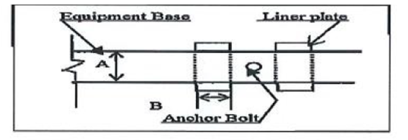
The length of pad shall be 20 mm to 30 mm longer than the width if the equipment bases.
After finishing padding work, following points shall be checked.
Position of center and elevation line of foundation
Elevation and position of pads
Cleanliness of concrete surface
Installation of Reciprocating Compressor
Installation sequence is based on Vendor’s Installation Manual and Supervision.
(Example of Vendor’s Installation Manual)
Lifting
Prior to the installation work, the foundation shall be checked for the following:
Location, orientation, elevation and conditions of support foundation conformed with Project plan Drawings
Level of pads on the chipped surface
Completely free from foreign material especially on chipped surface and anchor boxes
Concrete foundation has reached the curing period up until the compressive strength has reached 70% of the specified strength but not less than 7 days after placement
Prior to the installation work, the equipment shall be checked for the following points.
Compressor skid, Compressor, Cylinder Heads & other major components are free from any physical damage.
All components of the system such as relief valves and control valves. shall be identified with a permanently affixed corrosion-resistant tag showing the component identification number referenced to the piping and instrument diagram.
Rotation arrows shall be cast in or attached to each major item.
Prepare lifting location were the crane will be located and position.
Prepare and set all rigging accessories according to arrangement.
Checked wind condition, lift shall not proceed when wind velocity is greater than required of crane.
Stabilized ground areas where crane will be located and positioned. Crane mats shall be provided in accordance to findings of soil bearing pressure.
Crane lift & rigging requirement shall refer to Manual. The equipment shall be lifted by lifting lugs, lifting trunnion, tailing lugs or shell not by nozzles.
Equipment shall be protected by wooden blocks, rubber or other suitable material that will prevent equipment from damages caused by sling wire.
Install reciprocating compressors on the top of the foundation as per approved lifting plan.
Equipment shall be set and aligned at the proper position, elevation, levelness and perpendicularity in accordance’s with the drawing.
Grouting Method
Non-Shrink Grout for Auxiliary Equipment.
Prior to grouting, concrete repair have been performed in accordance with SAIC-Q-1062 as based on SAER-5803
Grout shall be mixed as per the Grout Manufacturer’s instructions.
Foundation preparation shall be in accordance with the grout manufacturer’s written instructions.
Concrete foundations shall be cured for a minimum of 7 days before surface preparations for grouting.
Laitance, oil-soaked or damaged concrete shall be removed down to sound concrete by chipping to the level of sound fractured aggregate or to a minimum of the top 1 inch (25 mm) of the concrete.
All dust and loose particles shall be removed with clean, dry, oil free compressed air.
Grout Formwork, where required, shall be constructed with adequate strength, rigidity and required dimensions to permit grout placement and avoid leakage.
A bond breaker shall be applied to the formwork that will be in contact with the grout.
After cleaning, the foundation shall be protected with 0.15mm polyethylene sheeting to prevent contamination.
Concrete surfaces in contact with the grout shall be saturated with clean water before grout placement. The surface shall be damp but free from standing water.
Joints in the grout shall be located as shown in the drawings or as recommended by the manufacturer.
Grout shall be placed in only one direction to prevent trapping air; Grouting shall be quick and continuous to avoid segregation, bleeding or premature initial set.
Re-tempering of grout adding water after stiffening is not permitted.
If the grout is placed through grout holes, it shall be placed from one hole continuously until the grout has passed a second hole. A liquid head pressure shall be maintained at the first access hole until a head pressure is established at the second hole and continued in a similar fashion until the next hole.
Grout shall be mixed, placed and cured in accordance with manufacturer’s written requirements. The contractor shall read, understand and comply with the manufacturer’s instructions as printed on each unit.
The grout shall be cut back to the lower edge of the base plate by 450 angle unless otherwise indicated.
Epoxy Grout for Compressor and Motor
Laitance and oil-soaked or damaged concrete are removed with chipping hammer to sound fractured aggregate, or to a minimum of the top 1 inch (25mm) of concrete.
Concrete chipping and removal shall not be performed with heavy tools such as jackhammers as they could damage the structural integrity of the foundations.
The minimum grout thickness under any portion of the baseplate/soleplate shall be 25mm.
Concrete in contact with the epoxy grout shall be clean, dry and oil free.
Formworks for epoxy grout are constructed to be liquid tight with adequate strength, rigidity and dimensions to permit epoxy grout placement.
Forms joints and interface between forms and concrete foundation are sealed with grout manufacturer’s recommended sealant.
Maximum depth of pour and length to width ratio shall be as per manufacturer’s recommendations.
Elevation of formworks shall be check to ensure that the top surface of the top surface of the grout will match the elevation shown on the construction drawings.
Three coats of paste wax shall be applied to the inside surface of the forms or other manufacturer recommended procedure for preventing bonding of the epoxy grout to the formwork.
Suitable shelter or enclosures shall be provided to protect the foundation and base plate from direct sunlight, dew, rain or other inclement weather. During cold weather, adequate enclosure and heating shall be provided to maintain foundation and base plate temperature with acceptable range specified by the grout manufacturer.
Expansion joints in epoxy grout shall be spaced at a maximum of 48 inches (1.4m) unless otherwise specified in the contract documents.
Expansion joints shall be made from closed-cell neoprene or polyethylene foam board, having a minimum thickness of 1 inch (25mm) unless otherwise noted in the contract documents.
Expansion joints shall be fixed into position to prevent movement and shall be sealed at formwork and at the concrete base to prevent epoxy grout from passing around or underneath the joint during placement.
All mounting plate/soleplate outside corners shall have a minimum of 50mm radius to prevent cracking of the foundation grout due to stress concentration at the corners.
Base plate leveling jack screws shall be provided with stainless steel leveling pads.
Mounting plate jackscrews shall be liberally coated with paste wax or grease to prevent grout adherence.
Suitable shelter or enclosures shall be provided to protect the grouted foundations from direct sunlight and weather.
Foundation and base plate temperature are within the acceptable range specified by the grout manufacturer until the grout has cured.
The grout shall be checked for voids after the grout has cured. Any voids shall be filled according to epoxy grout manufacturer’s recommendations.
After the void grout has cured, the base plate shall be recheck to ensure that all voids are filled with grout. Any voids still exist shall be rectified.
Exposed expansion joints shall be sealed with the epoxy grout manufacturer’s recommended sealant.
The final level of the epoxy grout is flush with the top horizontal chamfer edges built into the formwork.
TOOLS AND EQUIPMENT
Tools and equipment needed should be in good condition and must be checked by competent person and respective supervisor prior to use in the plant. Third Party vehicle and equipment inspections and vehicle stickers required. These includes but not limited to:
Calibrated engineering level with calibration certificate
Corrective wrenches all required range
Crane
Certified sling and hoists
Chipping hammer/bush hammer
Welding Machine
Compressor
Calibrated Alignment and Leveling tools
(Dial indicator, precision master level, other measuring equipment); Final shaft alignment shall be as per Vendor’s Recommended method.
Low-height rampack jacks
Chain block
Vendor-supplied tools, if any
Rubber mallet
Applicable International standard
API-618 – Reciprocating compressor for petroleum chemical & gas industry