This article is about INSTALLATION OF ELECTRICAL LIGHTING FIXTURES, RECEPTACLES AND WIRING DIVICES and focusing to the engineers, technicians and supervisors. You will find lot of documents related to this article. Just navigate our website www.paktechpoint.com and find more articles. Please! Do not forget to subscribe our You tube channel also. Thanks in Advance.


![]()
![]()
![]() PLEASE SUBSCRIBE OUR PAKTECHPOINT YOUTUBE CHANNEL
PLEASE SUBSCRIBE OUR PAKTECHPOINT YOUTUBE CHANNEL
![]()
![]()
![]()
INSTALLATION OF ELECTRICAL LIGHTING FIXTURES, RECEPTACLES AND WIRING DIVICES
Pre-installation Activities
- Ensure that all equipment to be transported from warehouse / lay down area to the work area complies with the project specifications.
- Check and test materials for damage before transporting to the work area. All materials of doubtful condition or quality shall be immediately segregated from the job site.
- Over hanging from the trailer / truck body of any materials is not allowed. Ensure that they are properly and adequately secured / supported.
- Ensure Safety Barriers are erected at designated work areas.For high elevation installation, ensure adequate scaffold ladders and access ways are available at the work location.
- Plan the work area with separate storage, work and waste disposal locations, to avoid congestion and enable systematic installation.
- Ensure proper safe work permit is received (if applicable) prior to starting the job and available with working crew.
- Conduits, cable tray shall be inspected & approved prior to any cabling.
- Contractor to comply with SAES-P-104 (Article 9.8)(ARAMCO standard), which states that for extending the cable from cable tray to equipment, the cable used should be armoured or metal clad and properly supported as per NEC or installed in rigid or flexible conduit.
- Cable sealing should be done by proper cable gland as per the requirement of SAES-P-104 (article 6 & 15). Which states that the following highlighted points.
6.7 All threaded cable fittings including terminators (glands) for metric size cables shall have tapered (NPT) threads in accordance with ANSI/ASME B1.20.1.
6.8 Cable glands shall be designed to permit disconnection without the need to rotate the cable or the equipment on which the gland is terminating (e.g., sealing glands shall have a built-in union).
6.14 Cable glands (for hazardous and non-hazardous locations) shall be in accordance with BS 6121 or BS 50262, except threads shall be in accordance with paragraph 6.8 above. In addition, cable glands for hazardous locations must comply with all applicable requirements of the NEC, SAES-P-100, and paragraph 15.3 below.
15.3 When cables entering enclosures are required to be sealed by the NEC, they shall be sealed by means of barrier type cable glands, utilizing sealing compound, (EEx d) or MI cable. These are called explosion proof glands by some manufacturers, flameproof by others. Flameproof (EEx d) non-barrier type cable glands, without sealing compound, are not acceptable.
10. Prior to installations, verify the suitability of lighting fixtures in accordance with area of classifications such as;
• Substation/PIS battery room fixtures shall be enclosed, gasket, vapour tight, corrosion resistant.
• In hazardous areas where the maximum daily ambient temperature exceeds 40 deg. C, the temperature code rating shall be based on an ambient test temperature of 50 deg. C or higher. Should the rated temperature is lower; it will affect the lighting components (ballast, capacitor & bulb).
Battery Room electrical installation
• Conduit & fittings must be resistant to the chemical present (acid). Therefore, RGS PVC coated shall be used (ref. SAES-P-104 para.4.3.) which states that “Locations where chemicals are being handled, enclosures, conduits, fittings, and wirings must be resistant to the chemicals present.”
• Electrical equipment shall not be located directly above the batteries and as a rule shall have a minimum horizontal separation of 1.5 meters from the nearest cell (ref. SAES-P-103 para.6.3.5.) which stated that “6.3.5 Equipment with arcing contacts shall be located in such a manner as to avoid those areas where hydrogen pockets could form. Electrical equipment shall not be located directly above the batteries and, as a rule, shall have a minimum horizontal separation of 1.5 meters from the nearest cell.“. Installations of receptacle outlet are also considered.
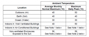
• The temperature criteria for outdoor Lightings (exposed to sun) shall comply with SAES-P-100 Table-2 which is given below
• Battery room lighting shall be installed to provide a minimum level of illumination level of illumination of 30-ft candles (300 lux) as per SAES-P-103.6.2.3.
• Battery room lighting fixtures shall be installed at least 300mm below the finished ceiling as per SAES-P-103 section 6.3.9.
- Emergency lighting with similar illumination level shall be installed to operate in the event of loss of main power supply as per SAES-P-103.6.2.3.
- As per SAES-P-104 section 5.10 cables for security lighting (perimeter and area lighting) shall be armoured or metal clad, installed underground and rising inside the lighting poles. See SAES-O-113.
- Wiring terminations and connections shall be as per SAES-P-104 section 6.
All interior substation lighting shall be fed from different power supplies dies (i.e. fed from two different low voltage switchgear bus) as per SAES-P- 119 section 6.8.
As per SAES-P-119 section 6. 7, Substation building exterior illumination shall consist of HID high pressure sodium type fixture controlled by a photo cell. A hand Off- Automatic (HOA) selector switch shall be provided in accordance with SAES-P-123 requirements for exterior illumination control.
Substation yard 120 VAC utility receptacles characteristics provided shall be as per SAES-P-119 section 7.8.
Ground fault circuit interruption for personnel shall be provided as required in paragraph 210.8(8) of NEC. The ground fault circuit interrupter shall be installed in a readily accessible location.
Installation Activities:
Ensure that approved installation procedure from Vendor manuals and Saudi Aramco specifications for the specific fixtures and devices to be installed are fully studied and understood prior to commencing installation.
Check the actual locations and mounting elevation prior to commencing the installation work.
Install the lighting fixtures, receptacles and devices following the vendor procedures and manuals.
Connect the lighting fixtures, receptacles and devices to the proper circuit as called for in the panel schedule.
Use the appropriate terminal lugs and connectors in terminating the lighting fixtures, receptacles, and wiring devices.
Install wire and cable markers indicating the identification number, panel board circuit number to where this fixtures, receptacles, and devices are connected.
Continuity and Megger test should be conducted, before all the lighting fixtures, receptacles and devices are terminated.
After all the lighting fixtures, receptacles and devices are terminated, a functional test is then performed to ensure that these are connected to the right panel board and circuit.
Ensure that the orientations of the lighting fixtures are correctly adjusted to attain an equally distributed level of desired illumination.
Perform the illumination test at any location to ascertain that the desired illumination level is attained.
Lighting Requirements shall be as per SAES -P-123 sections 4. 6.5 Lighting llluminance Levels shall be as per SAES-P-123 section 5.
References:
NFPA : National Fire Protection Association 2011
NEC : National Electrical Code 2011