This article is about Instrumentation Engineering and Design, Instrumentation Project Scope, P&IDs, In-Line Instruments, Non-In-Line Instruments, Instrumentation and Control Codes, Standards, and Specifications, Instrumentation Deliverables List, Instrument Calculation and Specification Sheets, Process Hook-Ups, Instrument Wiring Design, Instrument Earthing Systems.

1. Scope – The Engineering Contractor Representative shall perform the detailed engineering and design of the instrument and controls (I&C) system for the plant area or equipment package described in the contract scope for the project.
The contract scope will provide the details about the extent of the I&C work to be done and its required format. This work will include any one or more of the following tasks.
- Contributing to P&ID development.
- Specification and requisition of instrumentation, equipment, and materials.
- Technical management of purchase orders.
- Document control.
- Trip system design and specification.
- Control system specification, configuration, and commissioning.
- Instrument index preparation.
- Interfacing with packaged equipment including reviewing and commenting on package equipment drawings to ensure suitability and correct interfaces.
- Detailed design of instrument installations and generation of their drawings.
- Installation contract preparation and management.
- Handling plant site questions and resolving any resulting design problems for work done by the EC.
- Process commissioning of plant.
- Providing as-built records.
- Ongoing support through warranty period.
- Providing project progress and expenditure reporting and control.
9.1.2 Scope Summary
- The scope split table provided in 9.1.2.3 is a simplified example of the major I&C and associated activities to be performed on a project. It defines possible responsibilities for those activities. This is an example table only. The ENGINEERING CONTRACTOR must refer to the contract scope documents to understand the full extent of their I&C scope and responsibilities.
- If the ENGINEERING CONTRACTOR identifies any I&C-related activities necessary for successful project execution that have been omitted from the contract scope document, the ENGINEERING CONTRACTOR shall refer these activities to Companyfor resolution.
- Abbreviations that may be used in the table are defined below.
X – Executes the work, including generation of data as appropriate
I – Must be informed
A – Available to advise
C – Must be consulted
S – Specifies the work for others to execute (not including this specification)
D – Contributes some of the source data in support of work by others
– (****) Company discipline when other than I&C
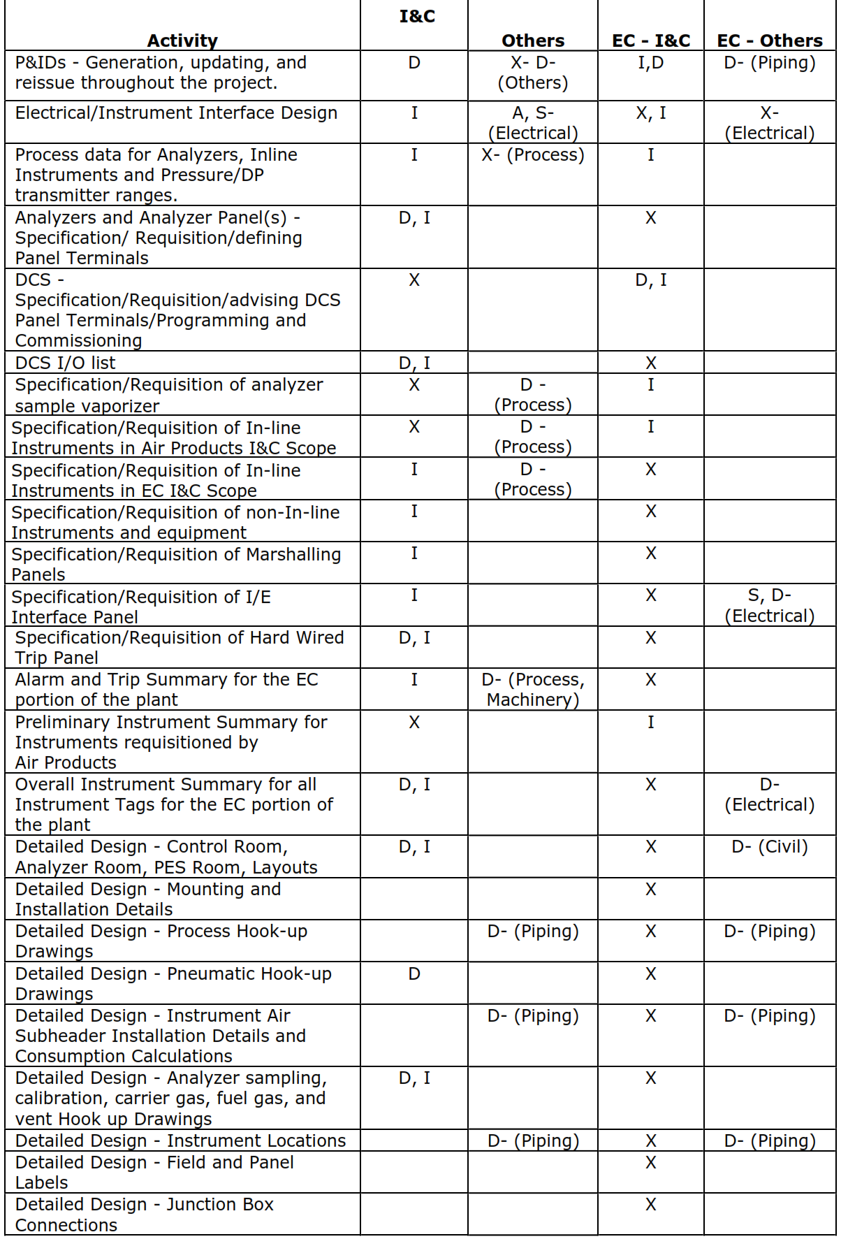
| Activity | Air Products – I&C | Air Products – Others | ENGINEERING CONTRACTOR – I&C | ENGINEERING CONTRACTOR – Others |
| P&IDs – Generation, updating, and | D | X- D- | I,D | D- (Piping) |
| reissue throughout the project. | (Others) | |||
| Electrical/Instrument Interface Design | I | A, S- | X, I | X- |
| (Electrical) | (Electrical) | |||
| Process data for Analyzers, Inline | I | X- (Process) | I | |
| Instruments and Pressure/DP | ||||
| transmitter ranges. | ||||
| Analyzers and Analyzer Panel(s) – | D, I | X | ||
| Specification/ Requisition/defining | ||||
| Panel Terminals | ||||
| DCS – | X | D, I | ||
| Specification/Requisition/advising DCS | ||||
| Panel Terminals/Programming and
Commissioning |
||||
| DCS I/O list | D, I | X | ||
| Specification/Requisition of analyzer | X | D – | I | |
| sample vaporizer | (Process) | |||
| Specification/Requisition of In-line | X | D – | I | |
| Instruments in CompanyI&C Scope | (Process) | |||
| Specification/Requisition of In-line | I | D – | X | |
| Instruments in ENGINEERING CONTRACTOR I&C Scope | (Process) | |||
| Specification/Requisition of non-In-line | I | X | ||
| Instruments and equipment | ||||
| Specification/Requisition of Marshalling | I | X | ||
| Panels | ||||
| Specification/Requisition of I/E | I | X | S, D- | |
| Interface Panel | (Electrical) | |||
| Specification/Requisition of Hard Wired | D, I | X | ||
| Trip Panel | ||||
| Alarm and Trip Summary for the EC | I | D- (Process, | X | |
| portion of the plant | Machinery) | |||
| Preliminary Instrument Summary for | X | I | ||
| Instruments requisitioned by | ||||
| Air Products | ||||
| Overall Instrument Summary for all | D, I | X | D- | |
| Instrument Tags for the ENGINEERING CONTRACTOR portion of | (Electrical) | |||
| the plant | ||||
| Detailed Design – Control Room, | D, I | X | D- (Civil) | |
| Analyzer Room, PES Room, Layouts | ||||
| Detailed Design – Mounting and | X | |||
| Installation Details | ||||
| Detailed Design – Process Hook-up | D- (Piping) | X | D- (Piping) | |
| Drawings | ||||
| Detailed Design – Pneumatic Hook-up | D | X | ||
| Drawings | ||||
| Detailed Design – Instrument Air | D- (Piping) | X | D- (Piping) | |
| Subheader Installation Details and | ||||
| Consumption Calculations | ||||
| Detailed Design – Analyzer sampling, | D, I | X | ||
| calibration, carrier gas, fuel gas, and | ||||
| vent Hook up Drawings | ||||
| Detailed Design – Instrument Locations | D- (Piping) | X | D- (Piping) | |
| Detailed Design – Field and Panel | X | |||
| Labels | ||||
| Detailed Design – Junction Box | X | |||
| Connections | ||||
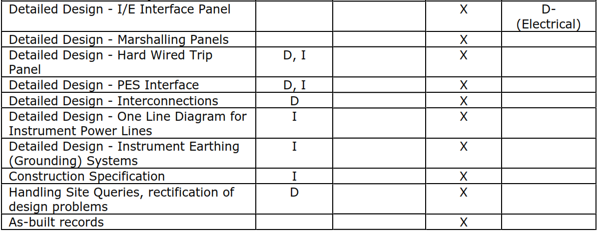
| Activity | Air Products – I&C | Air Products – Others | ENGINEERING CONTRACTOR – I&C | ENGINEERING CONTRACTOR – Others |
| Detailed Design – I/E Interface Panel | X | D- (Electrical) | ||
| Detailed Design – Marshalling Panels | X | |||
| Detailed Design – Hard Wired Trip | D, I | X | ||
| Panel | ||||
| Detailed Design – PES Interface | D, I | X | ||
| Detailed Design – Interconnections | D | X | ||
| Detailed Design – One Line Diagram for | I | X | ||
| Instrument Power Lines | ||||
| Detailed Design – Instrument Earthing | I | X | ||
| (Grounding) Systems | ||||
| Construction Specification | I | X | ||
| Handling Site Queries, rectification of | D | X | ||
| design problems | ||||
| As-built records | X | |||
1.3 Engineering Contractor Scope Clarification
- The following section provides greater detail for those activities listed above that require further definition and clarification of the ENGINEERING CONTRACTOR I&C scope. Any further clarification required by the ENGINEERING CONTRACTOR I&C should be requested through the Companyproject manager.
- The ENGINEERING CONTRACTOR I&C may offer the ENGINEERING CONTRACTOR standard formats as an alternative to typical Companydocumentation examples. However, the level of content and engineering detail must be equal to or greater than the examples given.
1.4 P&IDs
- The P&IDs will be updated throughout the project by either Companyor the ENGINEERING CONTRACTOR as stated in the specific scope of work document. The updates will be based on information supplied by the engineering disciplines. The EC’s contribution to the P&IDs might be limited to providing piping information to be added or might be extended to other process information.
- P&ID changes shall be identified by a P&ID change note before implementation.
1.5 In-Line Instruments
- The EC’s requisition scope for in-line instruments is as follows:
- The ENGINEERING CONTRACTOR I&C shall requisition all in-line instruments in pipework that will be designed by the EC.
- Company I&C will requisition all in-line instruments in pipework that will be designed by Air Products.
- In-line instruments are defined to include the following:
- Control valves
- Pressure control valves
- Relief valves
- Bursting (rupture) discs
- Flow measuring devices
- Temperature element/thermowell assemblies
- Temperature indicator/thermowell assemblies
- Variable area meters
- Level instruments
- Level gauges
- Level switches
- Thermowells
1.6 Non-In-Line Instruments
- The EC’s requisition scope for non-in-line instruments is as follows:
- ENGINEERING CONTRACTOR I&C shall requisition all non-in-line instruments in pipework whether it is to be designed by the ENGINEERING CONTRACTOR or by Air Products.
- Specific notes on the P&ID or elsewhere in the contract documents will indicate any exceptions to the above general rules.
- Non-in-line instruments include the following:
-
- Temperature transmitters
- Digital indicators
- Recorders
- Pneumatic controllers
- Pressure transmitters
- Pressure gauges
- Differential pressure indicators
- Differential pressure transmitters
- Receiver instruments
- Local annunciators
- Local air pressure regulators
- Solenoid valves (field)
- I/P transducers (field)
- Surge detectors
- Vibration monitoring equipment
- Trip amplifiers
- Speed monitors
- Manifolds
- Field-mounted switches and pushbuttons
2. Codes, Standards, and Specifications
2.1 Design Codes
The ENGINEERING CONTRACTOR shall design all instrumentation work in accordance with either the ENGINEERING CONTRACTOR or (NFPA #20) as stated in the contract scope. The ENGINEERING CONTRACTOR shall advise Companyif any local or country code takes precedence over the code noted in the contract scope before starting the design work.
2.2 Standards
9.2.2.1 Industry standards issued by the IEC, ANSI, or others shall be followed as appropriate to meet the design codes and/or Companyrequirements.
9.2.2.2 The Companyengineering standards and design guides relating to instrument design will be listed in the contract scope appendix.
2.3 Specifications
The Company specifications relating to instrument design will be listed in the contract scope appendix and used by the EC.
9.3 Company Deliverables to the Engineering Contractor
3.1 General
9.3.1.1 This section provides a general description of the typical drawings and documents that will be issued by Companyto the ENGINEERING CONTRACTOR as the basis for the detailed design work to be performed by the EC. Sometimes they will be drafts only. Additional deliverables may be required, and some deliverables may be deleted from a particular project. The contract scope will state the specifics for the project.
9.3.1.2 The contract scope appendix will list reference examples of the specifications and summaries where noted below for the EC’s use.
3.2 Instrument Specification – Design
This document will be issued as a project-specific document by Companyto define the project standards and requirements applicable to instrument engineering and design.
3.3 Instrument Specification Plant – Plant Data
This document will be issued as a project-specific document by Companyto define environmental and other data applicable to the site. The ENGINEERING CONTRACTOR shall note the requirements and conditions defined and provide a design that meets those conditions.
3.4 Preliminary Instrument Summary
- This document may be issued to provide an initial list of instruments in the project. The instrument summary provides information about the instruments and is one of the main design documents for the project. The ENGINEERING CONTRACTOR shall take responsibility to complete the information needed to provide the final instrument summary.
- If the project contract scope requires the use of SmartPlant Instrumentation (SPI) database (formerly INtools), the instrument summary shall be a report from the SPI database.
3.5 Engineering documentation
- Engineering documentation will be provided in support of the sections of plant engineered by Companyor will be made available to the ENGINEERING CONTRACTOR to enable the completion of engineering and design for the rest of the plant.
- This documentation may be:
-
- Process data sheets defining the process condition for instruments in the ENGINEERING CONTRACTOR scope (i.e., control valves, relief devices, analyzers, and flow elements).
- Instrument range requirements for pressure and differential pressure transmitters.
- Flow element calculations (for elements requisitioned by CompanyI&C).
- Level calculations to determine the differential pressure range for level transmitters for cold box vessels.
- Typical analyzers specifications and typical analyzer panel design data.
- PES panels/operator interface design data. PES terminal numbers (derived from PES I/O list produced by the ENGINEERING CONTRACTOR I&C).
- Design data sheets and supplier documents for instruments and valves requisitioned by CompanyI&C.
- Hard-wired trip system logic requirements.
- Layout drawings for Air Products-supplied areas showing location of interface points.
3.6 Preliminary Control Building Layout
This drawing will be prepared by Companyto show the approximate layout of panels and equipment internal to the building (marshalling cabinets, control and analyzer panels, PES consoles, etc.) and immediately external to the building (analyzer gas bottle rack, etc.). The ENGINEERING CONTRACTOR shall use this as the starting point for detailed layout drawings.
4. Deliverables from the Engineering Contractor
9.4.1 General
- This paragraph provides a description of the drawings and documents that shall be produced by the ENGINEERING CONTRACTOR and issued to Companyas the detailed engineering and design work is performed. Additional deliverables may be added to complete the project requirements.
- Examples of typical I&C documents are listed in the contract scope appendix. Company examples are supplied to provide minimum content requirements to the ENGINEERING CONTRACTOR I&C. The ENGINEERING CONTRACTOR I&C may follow the Company document format or may use their own standard document formats. However, the document content must be equivalent or more comprehensive than the examples supplied.
- Documents shall be issued to Company for information or for approval as defined in the table below. Company reserves the right to comment on any document whether issued for approval or for information.
| Description | Issued to Company for |
| Calculations, specifications, and data sheets for relief valves and bursting (rupture) discs requisitioned by the EC | Approval |
| Calculations, specifications, drawings, and data sheets for all other equipment requisitioned by the EC | Information |
| Bid lists and bid tabulations/analyses for relief valves and bursting (rupture) discs requisitioned by the EC | Approval |
| Bid lists and bid tabulations/analyses for all other equipment requisitioned by the EC | Information |
| Instrument summary – updated monthly | Information |
| Installation specification | Information |
| Drawings and documents listed below | Information |
4.2 Instrument Summary
- The ENGINEERING CONTRACTOR I&C shall maintain an up-to-date instrument summary or SPI database throughout the design phase of the project. The list shall be updated throughout the design phase to reflect the latest design data generated by the ENGINEERING CONTRACTOR I&C and received from Air Products. It shall be issued monthly. The instrument summary shall be issued as a working/control document in both electronic and paper form. The acceptable electronic format is Excel, which may be exported from SmartPlant Instrumentation as required.
- The instrument summary shall include each instrument tag on the entire project whether specified by the ENGINEERING CONTRACTOR I&C, CompanyI&C, package vendors, or others.
- For example, the following items in an instrument loop shall be listed on the instrument summary as five tags even though they are all associated with PT-1234 and some may be specified by the ENGINEERING CONTRACTOR and some by Company. “1FE” is an example of a unit operation code designation.
- 1FE-PT-1234 Pressure Transmitter
- 1FE-PT-1234 M Manifold
- 1FE-PI-1234 PES Pressure Indicator
- 1FE-PAH-1234 PES High Pressure Alarm
- 1FE-PAL-1234 PES Low Pressure Alarm
- Separate tag entries are required for the alarms so that an alarm list for the entire project can be produced from the instrument summary.
- The instrument summary shall include the fields as shown on the example document.
- There shall be as least the following three formal issues of the instrument summary:
- Defining PES I/O to enable CompanyI&C to requisition the PES (when required by the contract scope)
- On completion of design
- As-built
4.3 Instrument Calculation and Specification Sheets
Instrument calculation and specification sheets shall be produced by the ENGINEERING CONTRACTOR to size and specify valves and instruments. These shall then be used by the ENGINEERING CONTRACTOR to obtain bids so that the instruments can be purchased. These documents shall record all relevant technical requirements for the instrument or valve being specified. Typical instrument data sheets may be listed in the contract scope appendix as guidance to the content expected.
4.4 Control Room Layouts
- The ENGINEERING CONTRACTOR I&C shall design the layouts of the control room considering the following:
- Companybasic layout drawing (when relevant).
- Available space and room dimensions needed by operating personnel.
- Ergonomic considerations/operator convenience.
- Access for maintenance.
- Space for cabling and pipe routing and access as determined during design of the space.
- Details of the equipment to be located, whether supplied by Air Products, the EC, or others.
- These drawings are used as a reference when routing field tubing and cables to panels. They establish relative locations of equipment, internal and immediately external to the buildings. They are also used for routing analyzer vent headers and locating the gas bottle rack when relevant.
- A typical example of a control room layout may be given in the contract scope to assist the ENGINEERING CONTRACTOR in understanding the required content and format of this drawing.
4.5 Instrument Mounting Details
- The ENGINEERING CONTRACTOR I&C shall design the instrument mounting details. These details shall show how each instrument should be mounted.
- A drawing that shows a typical example of an instrument mounting detail will be listed in the contract scope appendix. The drawings produced by the ENGINEERING CONTRACTOR I&C shall be similar and shall contain at least the same level of detail.
4.6 Special Installation Details
These drawings supplement any standard installation details. They shall provide details of the required installation practices for issue to the construction contractor. The ENGINEERING CONTRACTOR I&C installation drawings must have sufficient detail to enable the construction contractor to fully complete installation without further clarification.
4.7 Process Hook-Ups
- These drawings shall be produced by the EC. They shall show process instrument tubing to be installed and piping connections to be made by the construction contractor in the field. These drawings are diagrammatic and do not imply actual (physical) orientations.
- These drawings are the basis for the design. The hook-up details shall be used by the ENGINEERING CONTRACTOR to develop the bill of materials.
- A drawing listed in the contract scope appendix will be a typical example of process hook-up drawings. It is intended to assist the ENGINEERING CONTRACTOR in understanding the required content and quality of this drawing. The format and level of content shall be consistent with this example.
- Impulse lines shall be designed in accordance with the instrument design specification.
4.8 Pneumatic Hook-Ups
- These drawings shall be produced by the ENGINEERING CONTRACTOR I&C. They shall show instrument air tubing connections to be made by the construction contractor in the field. These drawings are diagrammatic and do not imply actual (physical) orientations.
- These drawings are an integral part of the design. They shall be used by the ENGINEERING CONTRACTOR I&C to develop the bill of materials.
- A typical example of a pneumatic hook-up drawing is listed in the contract scope appendix. It is given to assist the ENGINEERING CONTRACTOR I&C in understanding the required content and quality of these drawings.
- The format and level of content of the EC’s drawings shall be consistent with this example.
4.9 Instrument Air Sub-header Installation and Routing Details
- These drawings shall be produced by the ENGINEERING CONTRACTOR I&C. They shall show the routing and installation details of the instrument air sub-header.
- A typical example of an instrument air sub-header routing detail is listed in the contract scope appendix. It is given to assist the ENGINEERING CONTRACTOR I&C in understanding the required content and format of these drawings.
- The ENGINEERING CONTRACTOR I&C shall use these drawings and the plot plan to complete their bill of materials and piping routing for the instrument air system.
- The ENGINEERING CONTRACTOR I&C shall produce consumption calculations for the instrument air system to demonstrate that the design complies with Air Products’ requirements.
4.10 Analyzer Sampling, Calibration, Carrier, Fuel Gas, and Vent Hook-Up Drawings
- These drawings shall be produced by the ENGINEERING CONTRACTOR I&C. They shall show the routing and details of the tubing and equipment associated with the analyzer system.
- A typical hook-up detail and a typical panel internal piping drawing will be listed in the contract scope appendix. The ENGINEERING CONTRACTOR I&C shall be responsible for the hook-up design external to and between the analyzer panels and for ensuring that the gases arrive at the analyzer panels appropriately conditioned. Analyzer sample systems shall generally be designed in accordance with Air Products’ specifications when noted in the contract scope appendix.
- The ENGINEERING CONTRACTOR shall develop the detailed design inside the analyzer panels in accordance with Companystandard 3PS05005. A typical example of an analyzer panel design will be listed in the contract scope appendix.
- Sample lines shall be designed by the ENGINEERING CONTRACTOR I&C to minimize response time and to ensure an adequate flow to each analyzer at the correct pressure. Hazardous lines, and specifically the hydrogen lines to sample analyzers, shall be fitted with flow restrictors in accordance with Companyspecifications when provided on a specific project.
- Moisture analyzer heads generally require field mounting. The ENGINEERING CONTRACTOR I&C shall design the hook- ups accordingly if heads are required.
4.11 Instrument Location Drawings
- These drawings shall show the physical location including the elevations of each field instrument. These drawings shall be produced by the ENGINEERING CONTRACTOR I&C. The ENGINEERING CONTRACTOR I&C is expected to base these drawings upon plot plans, piping, and equipment layout drawing.
- A typical example of an instrument location drawing is listed in the contract scope appendix. The EC’s drawings format shall be similar to the example and their level of content equal or greater.
4.12 Field and Panel Labels
These documents shall be produced by the ENGINEERING CONTRACTOR I&C for supply and installation by the construction contractor.
4.13 Panel Drawings
- These drawings shall be produced by the ENGINEERING CONTRACTOR I&C to support the technical specification and price quotation documents produced by the ENGINEERING CONTRACTOR I&C. The ENGINEERING CONTRACTOR I&C is responsible for both electrical and layout detailed design for the panels, not the panel manufacturers.
- PES (Programmable Electronic System) Interface
- The ENGINEERING CONTRACTOR I&C shall provide CompanyI&C with the PES I/O list including tags, description, signal type, and ranges based on the P&ID and Instrument design data. The PES I/O list shall include all points, including those where Companyhas detailed design responsibility.
- The CompanyI&C will use the PES I/O list to requisition and configure the PES and will provide the corresponding PES I/O terminations to the ENGINEERING CONTRACTOR I&C when required.
- The ENGINEERING CONTRACTOR I&C shall design the PES interface in accordance with the following signal types:
- PES Analog Inputs: 4-20mA isolated from ground. PES loop impedance is 250 ohms. Loops may be powered from the PES or from the transmitter.
- PES Analog Outputs: 4-20mA isolated from ground, powered from the PES. The PES is capable of driving a loop impedance of up to 600 ohms.
- PES RTD (Resistance Temperature Device) Inputs: 3-wire PT100.
- PES Digital Inputs: Volt-free contacts.
- PES Digital Outputs: Either 24V DC or volt-free contacts switching at up to 24V DC. Maximum current 0.5A.
4.15 Instrument Wiring Design
- These documents shall be produced by the ENGINEERING CONTRACTOR I&C to enable the construction contractor to install and terminate all field cabling and inter-panel cabling.
- The contract scope appendix lists an example of an instrument interconnections schedule to assist the ENGINEERING CONTRACTOR I&C in understanding the required content of this document. This example is typical of the interconnection drawings produced by CompanyI&C.
- The ENGINEERING CONTRACTOR I&C may provide interconnection drawings in the ENGINEERING CONTRACTOR I&C’s standard format if the functional requirements of the instrument interconnections schedule are met and the level of content is equal or greater than that of the Companydrawing example.
- Instrument signals shall be segregated from all AC power cables both in their cable runs and in junction boxes.
4.16 Single Line Diagram for Instrument Power Supplies
- This drawing shall be produced by the ENGINEERING CONTRACTOR I&C.
- The single line diagram for instrument power supplies shall be produced jointly by the EC’s and Air Products’ electrical disciplines. It shall include all instruments and panels whether supplied by Air Products, the EC, or others.
- The single line diagram shall be designed in accordance with the requirements of the appropriate standards listed in the contract scope appendix.
4.17 Instrument Earthing (Grounding) Systems
- The ENGINEERING CONTRACTOR I&C shall design the instrument earthing system in accordance with the requirements of the selected PES supplier and the specific country’s installation guidelines and codes Companywill provide the name of the selected PES supplier in the contract scope.
- The ENGINEERING CONTRACTOR I&C shall produce an instrument earthing specification and instrument earthing philosophy document for issue to the construction contractor.
4.18 Installation Specification (only when construction management is required by the contract scope)
- The ENGINEERING CONTRACTOR I&C shall produce the Instrument Installation specification. It shall include all instrument installation activities on the plant site in accordance with the specific country’s installation guidelines including:
- Physical inspection of instrument equipment.
- Pre-installation testing on site is specifically not required. The ENGINEERING CONTRACTOR I&C shall ensure that instruments are correctly supplied to site by checking supplier documentation and inspection in the supplier’s works.
- Installation including supply of installation materials.
- Testing.
- Precommissioning.
4.19 Construction Installation Management (only when construction management is required by the contract scope)
- The ENGINEERING CONTRACTOR I&C shall obtain price quotations, evaluate bids, and manage the construction contract for Air Products.
- The ENGINEERING CONTRACTOR I&C shall specify and manage the contract to ensure that the best and safest working and installation practices are used. The contract scope appendix lists a typical example of an installation specification. The installation specification produced by the ENGINEERING CONTRACTOR I&C shall contain at least the same level of detail and shall demonstrate at least the same quality standard of installation. The installation specification shall incorporate the same supplements and exceptions to the specific country’s installation guidelines as the sample specification.
- The ENGINEERING CONTRACTOR I&C shall ensure that the construction contractor’s installation is in accordance with the certification requirements of any hazardous area equipment.
- The installation specification shall include the following document:
-
- Contract schedule of rates to be completed by the construction contractor at time of price quotation (see example documents).
4.20 Installation Materials List
- This document shall be produced by the ENGINEERING CONTRACTOR I&C. The ENGINEERING CONTRACTOR I&C shall use their own design drawings to produce the required material list without further clarification. The installation materials list shall form part of the instrument installation specification.
- The installation material list shall contain sufficient detail to enable a third party construction contractor to bid for all installation materials without further clarification.
- The contract scope appendix lists a typical example of an installation materials list. It is given to assist the ENGINEERING CONTRACTOR I&C in understanding the required content and quality of this document.
4.21 Site Queries
- The ENGINEERING CONTRACTOR I&C shall handle all site queries about the areas within the EC’s responsibility during the course of plant installation and commissioning.
- The ENGINEERING CONTRACTOR I&C shall route queries relating to areas of Air Products’ responsibility to Air Products.
4.22 As-Built Records
The ENGINEERING CONTRACTOR I&C shall issue “as-built” versions of each design document and drawing incorporating all “as built” modifications on project completion.
5. Additional Technical Requirements and Guidance
These paragraphs define additional information intended to assist the ENGINEERING CONTRACTOR in understanding Air Products’ requirements and expectations from the contract. The ENGINEERING CONTRACTOR shall refer to the contract scope to understand the boundaries of their scope. Activities listed below are part of the scope of work as defined in the contract scope.
5.2 P&ID Symbols and Tags
- Company P&IDs use an ANSI representation of the plant instrumentation.
- Refer to Company standard 3SEF0520 for guidance in understanding the P&ID symbols.
- A valve type indicated on the P&ID may or may not be the valve type to be specified. A butterfly valve indicated on the P&ID, for example, merely indicates that a butterfly valve has been successfully specified for a similar duty on a previous project. However, line sizes and process conditions vary from project to project. The most suitable and cost-effective type for each valve shall be determined by calculation and with reference to standard 3PS40005.
- Any conflict between the P&ID symbol and other documentation should be reported to Companyfor resolution.
5.3 Packages and Plant Areas Designed by Others
- The ENGINEERING CONTRACTOR shall take full responsibility for understanding the instrument interfaces with other areas and packages specified but not designed by the EC. The ENGINEERING CONTRACTOR I&C’s design scope associated with these packages includes the following:
- Design of instrument interconnections between the package and the control system.
- Verification that E/I interfaces associated with the packages are consistent with the package design and comply with the P&ID.
- The following notes are for general guidance. However, the ENGINEERING CONTRACTOR I&C shall verify the actual details for each package and shall act accordingly:
- Local instrumentation will normally be supplied and installed on the package by the package vendor, so hook-ups for these items will not normally be required from the ENGINEERING CONTRACTOR I&C.
- Instrument signals to/from packages will normally be pre-wired to junction boxes on the packages by the package vendors. Instrument interconnections between package vendor junction boxes and package instruments need not be shown in the ENGINEERING CONTRACTOR I&C’s design documents.
- Package control will normally be via the PES.
5.4 Electrical/Instrument Interface
- The electrical/instrument interface refers to the interfaces between the control system and the switchgear in the MCC (Motor Control Center). Typical signals include start and stop from the PES and status signals to the PES.
- Company requires that these two systems are wired via an electrical/instrument interface panel. This panel shall have terminals for volt-free status contacts out of the MCC and 24 VDC relays for start /stop contacts to the MCC. Note that an electrical/instrument (E/I) interface panel is not required when the PES I/O cabinet for the interface is located in the MCC/switchgear room and is dedicated to the E/I interface signals.
- The ENGINEERING CONTRACTOR I&C’s design scope associated with the E/I interface includes the following:
- ENGINEERING CONTRACTOR Electrical in cooperation with ENGINEERING CONTRACTOR I&C shall produce a chart of electrical/instrument interfaces and switchgear schematic drawings. The ENGINEERING CONTRACTOR I&C shall ensure that the interfaces comply with the requirements defined on the P&IDs and vendor package data.
- Detailed design of the E/I interface.
- Enquiry package and bid tab to allow procurement of this panel in the appropriate country as required.
- Interconnections between MCC cubicles and the E/I interface panel shall be designed by the EC.
5.5 Specification/Requisition
- The ENGINEERING CONTRACTOR I&C shall perform the following activities as appropriate when specifying and requisitioning equipment:
-
- Calculations; working with CompanyProcess Engineering; revisions as required.
- Production of technical specification and data sheets.
- Compliance of in-line items with the requirements of the appropriate piping specifications.
- Preparation of technical specification documents for price quotation. (Price quotation to be organized by the ENGINEERING CONTRACTOR Procurement.)
- Technical bid analysis (commercial bid analysis by the ENGINEERING CONTRACTOR Procurement).
- Preparation of technical specification documents for order. (Order placement/procurement to be organized by Air Products.)
- Technical management of purchase order (answering supplier queries).
- Verification, correction, and approval of supplier documentation.
- Inspection.
- The ENGINEERING CONTRACTOR shall use competitive price quotation to obtain competitive quotes for the supply of equipment.
- The contract scope will include a list of Company”normal suppliers” and indicates those commodities for which Companyhas global supply agreements. The ENGINEERING CONTRACTOR should try to include the Companypreferred/global suppliers but is encouraged to include similar suppliers, especially if they have in-country manufacturing capability.
- All instruments shall be requisitioned in accordance with the requirements of the instrument design specification and plant data sheet.
9.5.6 Supplier Documentation
- The minimum requirements for supplier documentation shall include as appropriate:
- Material certificates for all in-line pressure-containing parts as required by the contract scope
- Calibration and test certificates
- Instruction manuals
- Recommended spares list
- General Arrangement (GA)/dimensional/installation drawing
- Hook-up drawing detailing connections of auxiliary equipment
- The ENGINEERING CONTRACTOR shall operate a supplier document control system to keep track of documents received and of their approval status and shall expedite supplier documents as necessary to maintain the overall project schedule.
5.7 Spares (when required by contract scope)
- The ENGINEERING CONTRACTOR I&C shall requisition sufficient spare items of equipment for commissioning. Spares shall be requisitioned at the same time as the main equipment to benefit from any discounts that have been offered. The ENGINEERING CONTRACTOR I&C shall determine the spares requirement based on:
- The ENGINEERING CONTRACTOR I&C’s experience on the most cost-effective level of spares holding while ensuring that start-up will not be adversely affected by non-availability of spares.
- Suppliers’ spares recommendation.
- Any contract statements from Companyon spares holding requirements.
- The ENGINEERING CONTRACTOR shall obtain supplier spares quotations for two years’ operation and shall transmit the quotations to Air Products. The ENGINEERING CONTRACTOR I&C is not required to procure spares for two years’ operation.
5.8 Equipment for Oxygen Duty
- The ENGINEERING CONTRACTOR I&C shall ensure that all materials are compatible with oxygen service when specifying equipment for oxygen duty.
- The ENGINEERING CONTRACTOR I&C shall ensure that all instruments and valves for oxygen duty comply with Company requirements as defined in standard 3PS00016. This includes metals, soft parts, and lubricants suitable for oxygen service. Company will provide project-specific specifications when required. Company shall give final approval of all oxygen service valves.
- All valves and instruments intended for oxygen service shall be cleaned to the requirements of specification 4WPI-SW70003.
5.9 Cleaning Specifications
The ENGINEERING CONTRACTOR I&C shall specify that instruments are cleaned by the supplier as required by standard 3PS35002.
5.10 Temperature Indicator/Thermowell Assemblies
The ENGINEERING CONTRACTOR I&C shall determine suitable temperature indicator ranges from the P&ID line specification and process specification. Refer to Companystandard 3PS15004 for temperature indicator requirements.
5.11 Pneumatic Pressure and Flow Controllers
The ENGINEERING CONTRACTOR I&C shall specify Foxboro Model 43AP pressure and flow controllers where pneumatic controllers are required on the P&ID.
5.12 Pressure, Flow, Level and Differential Pressure Transmitters
- Transmitters shall be selected and installed generally in accordance with standard 3PS00007 and specification 4WPS-INST01.
- The ENGINEERING CONTRACTOR I&C shall determine ranges as follows:
-
- Pressure transmitters – from the design pressure of the line and working pressures from the P&ID line specification and process specification.
- Differential pressure-type flow transmitters – from the flow element calculations performed by the ENGINEERING CONTRACTOR I&C and CompanyI&C.
- Differential pressure-type level transmitters – from level calculations. CompanyI&C will perform the calculations for vessels inside cold boxes; EC-I&C shall perform other calculations.
- Differential pressure transmitters (e.g., across filters, pumps) to be determined by the ENGINEERING CONTRACTOR I&C.
5.13 Pressure Gauges
- The ENGINEERING CONTRACTOR I&C shall determine suitable pressure gauge ranges from the design and working pressures of the line.
- Pressure gauges shall be in accordance with the standard listed in the contract scope appendix.
5.14 Differential Pressure (DP) Gauges
- The ENGINEERING CONTRACTOR I&C shall determine suitable differential pressure gauge ranges for differential pressure transmitters (above). Differential pressure gauges shall be designed to withstand the full line design pressure on either side of the differential pressure cell without loss in calibration.
- The ENGINEERING CONTRACTOR I&C should consider using differential pressure transmitters with local displays instead of differential pressure gauges if it would result in a lower total installed cost to Companyor greater accuracy and/or reliability at no greater cost.
5.15 Flow Elements
- The specification/requisition process shall include performing sizing calculations to ISO 5167 based on process data sheets produced by CompanyProcess Engineering.
- The sizing calculation shall be repeated as necessary to arrive at the optimum solution taking the following factors into account:
- Compliance with ISO 5167 validity limits.
- Compliance with process specification.
- Selection of differential pressure span. The default is 200 mbar. However, the minimum span for paymeters shall be greater than 50 mbar and the minimum span for any other meter shall be greater than 20 mbar. Air Products’ approval is required before specifying spans below these limits.
- Specification of low-cost elements wherever possible. If the process specification can be satisfied in all respects except unrecoverable pressure loss by using an orifice plate, the ENGINEERING CONTRACTOR I&C shall request that the process specification requirements be decreased before specifying a more expensive low loss device.
- Ensuring adequate upstream and downstream straight sections to achieve the accuracy specified on the process data sheet.
- Any unusual requirements, such as reverse flow measurement or high turndown, that may require multiple transmitters shall be considered by the ENGINEERING CONTRACTOR I&C in selecting the number of DP cells and DP cell ranges.
- Flow elements for paymeters shall be designed in accordance with 3PS25010 with flow compensation and integration performed in the PES. Complete paymeter systems shall be designed to ensure that the total system accuracy meets the requirements of this specification over the specified operating range of the instrumentation and over the full range of ambient conditions.
5.16 Control Valves and Self-Regulating Pressure Control Valves
- Control valves shall be sized and specified in accordance with standard 3PS40005 and purchased generally in accordance with the 4WPS-VALVXX series of purchase specifications as listed in the contract scope appendix.
- The specification/requisition process shall include:
- Perform sizing calculations based on process data sheets produced by Air Products Process Engineering.
- Selection of valve type in accordance with standard 3PS40005.
- Selection of valve Cv in accordance with the valve selection Cv constraints in standard 3PS40005.
- The sizing of safety valves is often limited by the Cv of control valves installed in the protected system. Therefore, before order placement, review recommended supplier’s actual Cv with reference to any Cv assumptions stated in relief valve process data sheets issued by CompanyProcess Engineering. Resolve any differences with CompanyProcess Engineering and amend the technical specification as necessary. Feed back actual CVs to CompanyProcess Engineering.
- Valve inspection and testing at supplier’s works. The inspection and testing requirements shall be as strict as the example given in Companytypical quality plans.
- The ENGINEERING CONTRACTOR is responsible for the design of silencers and any associated control valves.
- Controlled gas vent and compressor recycle systems shall be designed in accordance with Company specifications or code standards per the contract scope appendix.
5.17 Solenoid Valves, I/P Transducers, and Local Air Pressure Regulators
Solenoid valves, I/P transducers, and local air pressure regulators should normally be specified as part of the control valve assembly. Solenoid valves shall be tagged independently from the associated control valve. Alpha components of tags shall be as follows:
-
- *X Solenoid Valve, where * is the first letter of the associated control valve tag.
- I/P converters or electromechanical positioners shall be tagged as part of the control valve.
5.18 Relief Valves
- Relief valves shall be purchased in accordance with specification 4WPI-EW80010 for full flow safety valves. Cryogenic thermal relief valves shall be provided in accordance with Company requirements if needed for a specific project.
- The specification/requisition process shall include:
- Sizing calculations based on process data sheets produced by Company Process Engineering and in accordance with referenced Companystandards and specifications.
- Preparation of technical specification documents for price quotation. Valve specifications shall comply with 3SEV0901 or other project-specific requirement as given in the contract scope, ASME VIII, and API RP 526.
- Technical bid analysis.
- Preparation of technical specification documents for order. (Order placement to be organized by the ENGINEERING CONTRACTOR Procurement.)
- Feedback of recommended supplier’s actual relieving capacity to CompanyProcess Engineering for review before order placement. ENGINEERING CONTRACTOR Piping must also submit piping isometrics of selected lines for review before the relief valves may be ordered.
- Companyshall approve all relief valve calculations and specifications.
5.19 Bursting (Rupture) Discs and Holders
- Bursting discs shall be purchased in accordance with specification 4WPI-EW80015.
- The specification/requisition process shall include:
-
- Sizing calculations based on process data sheets produced by Company Process Engineering in accordance with standard 3SEV0902.
- Bursting discs shall comply with specification 4WPI-EW80015.
- The number of discs requisitioned per disc holder shall be calculated as defined in specification 4WPI-EW80015.
- The ENGINEERING CONTRACTOR I&C shall witness tests as defined in specification 4WPI-EW80015.
5.20 Temperature Element/Thermowell Assemblies
- Company specification 4WPS-TEMP06 will be issued to the ENGINEERING CONTRACTOR for guidance. The ENGINEERING CONTRACTOR may follow this specification or offer other technically equivalent alternatives.
- Company prefers that the ENGINEERING CONTRACTOR I&C specify and requisition PT 100 platinum resistance thermometers (RTD) rather than thermocouples wherever possible.
- The ENGINEERING CONTRACTOR I&C shall specify and requisition all RTD elements as duplex 3-wire elements. Only one of the duplex elements shall be wired back to the PES.
- RTD elements shall be wired to the control system as 3-wire. Temperature transmitters are generally not required.
5.21 Instrument Manifolds
- Manifold valves shall be specified for pressure and differential pressure instruments as defined in standard 3PS40002.
- Specification 4WPS-VALV10 is issued to the ENGINEERING CONTRACTOR for guidance. The ENGINEERING CONTRACTOR may follow this specification or offer other suitable technically equivalent alternatives.
- Manifold valves shall be purchased loose to be fitted on site by the Installation Contractor.
5.22 Installation Materials
- The ENGINEERING CONTRACTOR I&C shall specify/requisition all instrumentation cables except cold box RTD cables for the project. Cold box RTD cables (i.e., special RTD cable suitable for running inside the cold box) will be specified and requisitioned by Company I&C.
- Cable quantities shall be calculated from the instrument installation materials take-off and shall include suitable allowance for terminations, drum lengths, etc. Cabling shall comply with the requirements of the instrument design specification.
- Multi-triad cables used for RTD signals shall have individually screened triads and an overall screen.
- The ENGINEERING CONTRACTOR I&C shall specify other installation materials. The ENGINEERING CONTRACTOR I&C shall ensure that other installation materials are requisitioned and are available on site before they are needed. The ENGINEERING CONTRACTOR I&C shall requisition long delivery materials that the construction contractor would have insufficient time to requisition. Short delivery materials may be supplied by the construction contractor in accordance with the ENGINEERING CONTRACTOR I&C’s installation specification.
5.23 Analyzer Regulators
The ENGINEERING CONTRACTOR I&C shall specify and requisition all analyzer regulators in accordance with standard 3PS05005. The ENGINEERING CONTRACTOR I&C shall specify Tescom regulators.
5.24 Panels and Marshalling
- The ENGINEERING CONTRACTOR I&C shall design, specify, and requisition all panels in accordance with the particular requirements of the country in which the panel will be installed.
- All panels shall be designed to include:
- Sufficient terminals to terminate all cores of multi-core cables entering the panel, together with a minimum of 10% further spare terminals for future expansion.
- 20% usable free space for future expansion.
- All equipment within panels having exposed terminals or contacts that carry voltages greater than 24 volts shall be further enclosed or shielded with plastic guards to protect personnel per the electrical code minimum requirements with the enclosure door open. Low voltage signal wiring shall be run in plastic or metal ducting with snap-on covers.
- The hard-wired control panel shall be painted to match the PES supplier’s standard panel finish. Other panel finishes shall be semi-gloss light blue. The inside of the panel shall be painted with one priming coat and two coats of gloss white enamel. Hold panel color requirements are to be defined during project execution.
- Compliance with the instrument earthing and power philosophy, including provision of both clean earth and power earth bars.
- Adequate maintenance access shall be provided. Access requirements shall be included in both the panel and room layout designs.
- It is expected that all panels will be manufactured in the country of installation. The ENGINEERING CONTRACTOR shall arrange for full functional testing and inspection of panels at the panel fabricator’s works. Company reserves the right to participate in these inspections.
5.25 Marshalling Panels
- The ENGINEERING CONTRACTOR I&C shall carry out the detailed design, specification, and requisitioning of the marshalling panels, to gather the signals going to and from the PES cabinets and trip panel. The design shall include a way of jumpering signals that allows flexibility to reroute signals as necessary during commissioning. The marshalling panels shall include any necessary signal isolation/conversion modules that may be required to interface between the field, PES, and other panels. Examples of modules include:
- Relays for proximity limit switches used on some valves.
- Signal isolation required where analog signals to the PES are not isolated from ground.
- The I/E interface panel may be a separate marshalling panel or may be integrated with the other marshalling panels. The I/E interface panel shall be designed to terminate all cores from the MCC, plus the spares allowance noted above.
- The cables from the MCC to the I/E interface panel shall be the responsibility of ENGINEERING CONTRACTOR Electrical. The ENGINEERING CONTRACTOR I&C shall allow for 19 cores for each MCC item (e.g., pump, motor).
5.26 Junction Boxes
The ENGINEERING CONTRACTOR I&C shall perform the detailed design of field junction boxes. The junction boxes will be requisitioned by the construction contractor.
5.27 Trip Panel
- The ENGINEERING CONTRACTOR I&C shall perform the detailed design, specification, and requisitioning of the hard- wired trip panel, based on the trip logic requirements to be defined by CompanyI&C.
- The trip logic shall be constructed either as hard-wired logic gates or hard-wired relay logic.
- A hard-wired trip panel shall be considered to have 50 inputs, 20 outputs, plus associated overrides.
5.28 Analyzer Panel
The ENGINEERING CONTRACTOR I&C shall perform the detailed design, specification, and requisitioning of the analyzer panel, based on the analyzers list and sample stream requirements shown on the project P&ID.
5.29 Air Products-Supplied Panels
Some panels may be supplied without charge to the ENGINEERING CONTRACTOR I&C by Company I&C, such as PES panels/consoles. All Air Products-supplied panels will be specified in the contract scope. The ENGINEERING CONTRACTOR I&C is responsible for specifying the installation of inter-panel wiring and pipework.
9.5.30 Analyzer Bottles
The ENGINEERING CONTRACTOR I&C shall specify and requisition calibration, carrier, and fuel gas bottles for the analyzer system in accordance with standard 3PS05016. The ENGINEERING CONTRACTOR I&C shall requisition a spare bottle for each bottle required for commissioning.
5.31 Instrument Suppliers
The contract scope will include a listing of instrument types and their associated required suppliers. The ENGINEERING CONTRACTOR shall use these suppliers for the instruments that they specify.