INTERMEDIATE TRAY INSPECTION CHECKLIST
Information in this paragraph are typical points to check on site during loading. Up-to-date inspection sheets will be provided on site by start-up manager.
INTERMEDIATE TRAY INSPECTION POINTS | TOWER INTERNALS
Following are steps to inspect and install intermediate tray in tower internals.
-
PANEL INSTALLATION
- Container opening / Panel laying down on outside trestles at ground.
- Panel punch mark checking & cleanness inspection.
- Panel Upper & lower screen inspection at ground.
- Panel nozzle closure with plastic caps.
- Neoprene sheet installation on panels.
- Panel lifting & laying down on beams.
- Panel positioning with metal spacers.
- Panel rocking detection / Shim plate tack welding.
-
ROPE PACKING
- Panels – Shell – Centre pipe Rope packing.
- Tray cleaning.
-
PANEL SEALING
- Clip adjustment & positioning / Tack welding / inspection.
- Clip welding / inspection.
-
BEAM INSTALLATION
- Beam laying down on trestles at ground.
- Beam punch-mark checking & cleanness inspection.
- Main beams installation / positioning / centering.
- Main beam levelling / rocking / Shim plate tack welding.
- Secondary beam installation / positioning / centering.
- Secondary beam levelling / rocking / Shim plate tack welding.
- Main beam – Centre Pipe – Axis paint Marking.
-
INTERNAL PIPING & CENTER PIPE BLANKET INSTALLATION
- Internal piping preparation / inspection.
- Installation/ bolting.
- Centre Pipe Blanket installation.
-
FIXED THERMOCOUPLE VERIFICATION (BED 1, 6, 11, 13, 18, 23)
- Verification of flexible thermocouple in their position.
-
TRAY CLEANING & FINAL INSPECTION
- Tray final cleaning & removal of Neoprene sheets.
- Screen vacuum cleaning.
- Screen – Clip – Bellows – Beam – Cleanness inspection.
- Collecting data for bed volume calculation.
-
TRAY SIEVE LOADING
- Loading Hopper installation / Catapac centering – positioning – testing.
- Sieve loading / intermediate inspection / sampling.
- Bed levelling / Adjusting sieve quantity / Catapac platform air blowing.
Please check out this related article also: LOWER TRAY INSPECTION POINT | TOWER INTERNALS
TRAY PANEL INSTALLATION
| Procedure | Hold points |
| – Preparation Panels are laid down on trestles at ground. Punch mark & screen status carefully inspected. Check the inside of the tray panels by removing the plastic cap, blow dry air or vacuum clean if necessary At ground, all nozzles covered with plastic cap. Neoprene sheets taped on screen. |
Lower & upper screen panel inspection ‘Neoprene sheet taped with adhesive tape Nozzle covered with plastic cap Cleanness inside the tray panels Angle bars welded on trays near the center pipe |
| Overall Cleanness Wear shoes protection before starting the tray panel installation to avoid damaging the sieve and bring dirt inside the adsorbers. |
Upper face of beams Upper face of support rings Upper face of annular chambers |
| – Sequence of panel introduction Axens inspector must be inside before starting the introduction of the 1 panel. Follow the sequence carefully for proper positioning on the support beams. – Lower panel screen Before positioning, each lower tray panel screen must be inspected carefully with a flash light ( check for damages done during handling) – Flatness and stability of panels Check the good contact between the panels, the beams and the support rings. If there is any rocking, insert and tack weld shim plate on outside edge of the frame. |
Panels 1 A to 8B |
| – Gap between panels Install spacers for positioning and maintain the position with screw clamps. |
Gap between panels must be 15 mm Maximum. |
| – Gap between panels and shell Maintain a minimum gap on shell side for the rope. At the end of the panel installation, shoes protection can be removed |
Gap between panels and shell must be 10 mm Mini. |
ROPE PACKING
General remark:
Because of the poor roundness of the shell, the diameter of the rope to be used shall be adjusted (30, 20, 8mm) according to the gap available especially between the panels and the shell. The rope packing shall be done smoothly to avoid damaging the rope.
| Procedure | Hold points |
| – Rope packing : Rope packing must be done following a specific sequence given by Axens. Use the recommended rope packing tools. Check that the rope used for the previous bed is in a good conditions (dry and clean) |
Rope wrapping & status ( clean and dry) & type & diameter No free space between panels Last row must be flush to the upper edge of panel frame |
| – Rope packing between panels The first row must be packed carefully against the rope arrestor in order to prevent the rope going through it. |
Last row of rope must be flush to upper edge of panel frame. Gap after rope packing: 15 mm Max between panels |
| Last row of rope must be flush to upper edge of panel frame. Gap after rope packing: 15 mm Max between panels |
Rope packing between center pipe and panels |
| – Rope packing between panels and shell Install 1 row of rope to compensate the height of rope arrestor. If clearance between shell and panels is larger than 25 mm, then install 30 mm and 8 mm diameter ropes if necessary. If clearance smaller than 8 mm, then install 8 mm diameter rope. Complete the rope filling up to the top of panel frames. |
Last row of rope must be properly Inserted. |
| – Tray cleaning All rope debris and dust shall be removed. Pack the remaining rope care/ ully in a clean and dry plastic bag. |
Cleanness Remaining Rope wrapping status |
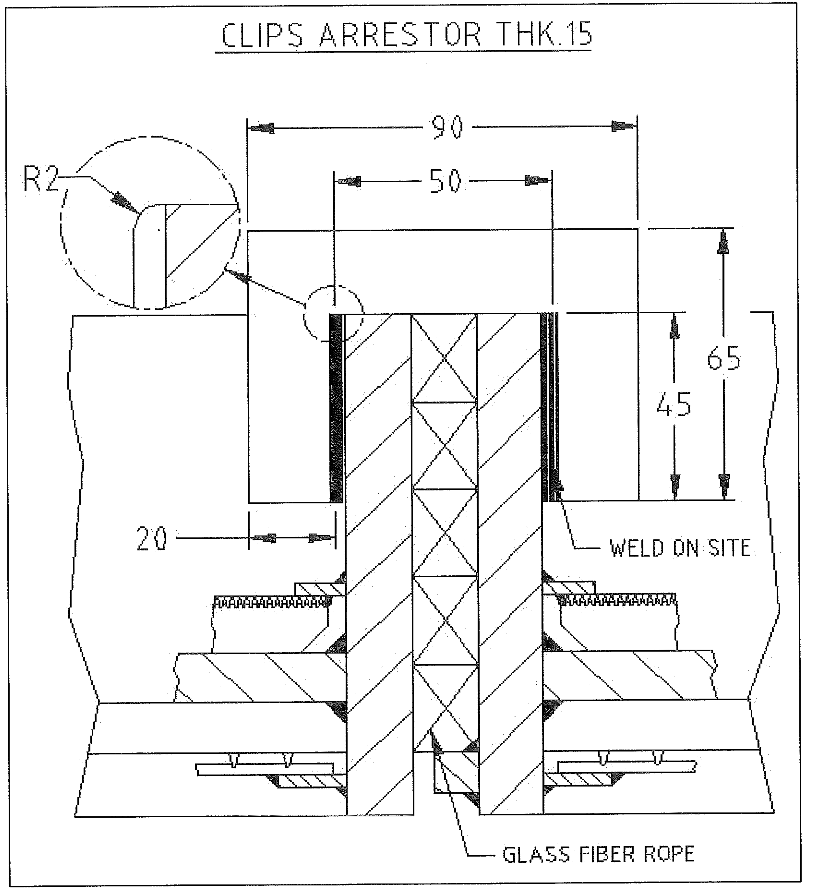
| – Clip position paint marking As following the clip arrestor arrangement scheme, indicate on both side of the panel frame the position of the clips |
Paint marking on the tray panels |
CLIP INSTALLATION
| Procedure | Hold points |
| – Clip installation Position clip according to Axens recommendations (paint marks). Typical pitch between 2 clips = 500 mm. Install the clip perpendicular to the frame. If the gap between the clip and the frame is larger than 3 mm on each side, turn the clip in order to get 2-3 mm between the clip and the frame to ease the welding Tack weld. |
Location of clips after tack welding Minimum gap between Clip-screen: 5 mm min. Clip perpendicular to the frame panel. Clip position after tack welding |
| Clip welding | Welding quality |
TRAY SUPPORT BEAM INSTALLATION
| Procedure | Hold points |
| – Preparation The support beams are laid down on trestles at ground. Punch mark carefully inspected. |
Cleanness (no rust) Number of support beams Punch Mark |
| – Main beam installation During beam installation, Axens inspector must supervise the beam installation from inside the tower if possible. To check level, flatness of the upper surface and alignment use spirit levels (short and long). In case of beam rocking, shim plates of different thickness must be used and tack welded on support beam. Signed up on all checking points with a paint marker as following Axens marking procedure |
Rocking Centering of the beam inside support (delta max: 1 mm). Centering of the beam between the 2 supports (delta max: 5mm). Level (2 directions)Alignment: – beam upper face with center pipe support ring (delta: 3 mm Max.) – beam upper face with shell support ring (delta: 3 mm Max) Checking Marks on the beam, shell & center pipe. |
| – Secondary beam installation During beam installation, Axens inspector must supervise the beam installation from inside the tower if possible. To check level and alignment use spirit levels. In case of beam rocking, shim plates of different thickness must be used and tack welded on support beam. Signed up on all checking points with a paint marker as following Axens marking procedure Follow the Axens sequence of installation |
Rocking Centering inside support ( delta max: 1 mm) Centering between the 2 supports(delta max: 5mm with the shortest distance between beam angle and shell).Level (2 directions) Alignment: – beam upper face with center pipe support ring ( delta : 3 mm Max.) – beam upper face with shell support ring ( delta : 3 mm Max) Checking Marks on the beam, shell & center pipe |
| – Axis tracing Trace main beams axis only using a ruler with a paint marker. Using as reference, on each side of the center pipe, the middle of the length between the two longest secondary beams, mark up the center pipe and the shell for further vessel dimension measurement at 700 mm from the screen. |
Axis paint marking on Main beam axis, shell & center pipe. |
INTERNAL PIPING
| Procedure | Hold points |
| Internal piping inspection at ground Check the punch marking, number and status of the piping at ground or on the top platform. |
Conditions ( clean, dry, no rust, no iron filings) Protection of the bellows w/ PVC tube Number, type of the piping |
| Installation of the piping Install the piping with final gasket. Perform a thorough inspection and check all the bellows (alignment, tension). Bolt and tighten the flanges. |
Visual inspection (tension and alignment of bellows) Flexible hose installed length (welding line to welding line) to be checked to be between 430 and 470 mm. Bolting Tightened Verification of the final gasket installation |
CENTER PIPE BLANKET INSTALLATION
| Procedure | Hold points |
| – Center pipe blanket Follow the Axens procedure |
Bolting of the grip collars (top and Bottom). Tackweld on bolts. Blanket conditions after installation No free space at the seam location. |
FIXED THERMOCOUPLE VERIFICATION ON BED 2, 6, 12, 14,18, 24
| Procedure | Hold points |
| Check any damage on the thermowell Pack some rope in the nozzle to minimize dead volume |
Status of the thermowell Rope packing in the nozzle |
TRAY FINAL CLEANING
| Procedure | Hold points |
| – Preparation Remove the section of ladder present in the bed Remove all debris and tools. Vacuum clean the neoprene sheets before removal. Remove all neoprene sheets and vacuum clean the screen. Wear shoes protection before starting the tray final cleaning to avoid damaging the screen |
Cleanness before Neoprene sheet Removal Shoes protection to be worn all the time Bed free of ladder |
TRAY FINAL INSPECTION
Items for inspection : Laser meter, ruler (3m), pen, wrench XX, spirit levels (short & long), flash light, Axens tray doc., small knife
| Procedure | Hold points |
| – Adsorber conditions Dry air must be blown to ensure a dry atmosphere before sieve loading |
Dry air in service Access to bed during loading Hoist chain to be removed at bottom |
| – Ladder | Bed free of ladder |
| – Screen status & slot spacing | Slot spacing checking with feeler gauge |
| – Rope packing | Rope packed everywhere |
| – Clips | Position / distance between clip & screen Welding |
| – Beam conditions Walk on it to detect any rocking |
Rocking Level Axis marking (beam axis) |
| – Internal piping Look for any uncompleted work, absence of gasket, damaged bellow. |
Bolting (checked with a wrench) Gasket type Bellows tension, status of the protection |
| – Blanket around center pipe | Installation & seam quality |
| – Cleanness Look for remaining tools, dye stains, welding stains. In case of dust or dirt, ask for more cleaning (vacuum cleaner). |
Shell / center pipe Upper part of beams Support Ring on center-pipe I shell Screen surface |
| – Thermocouple | Position |