LOWER TRAY INSPECTION SHEET
Information in this paragraph are typical points to check on site during loading. Up-to-date inspection sheets will be provided on site by start-up manager.
LOWER TRAY INSPECTION POINT | TOWER INTERNALS
-
BEAM INSTALLATION
- Beam laying down on trestles at ground.
- Main beams installation / positioning / centering.
- Main beam leveling / rocking / Shim plate tack welding.
- Secondary beam installation / positioning / centering.
- Secondary beam leveling / rocking / Shim plate tack welding.
- Main beam — Center Pipe — Axis paint Marking.
-
PANEL INSTALLATION
- Container opening / Panel laying down on outside trestles at ground.
- Panel punch mark checking & cleanness inspection.
- Panel Upper screen inspection at ground.
- Panel nozzle closure with plastic caps..
- Neoprene sheet installation on panels.
- Panel lifting & laving down on beams.
- Panel positioning with metal spacers.
- Panel rocking detection / Shim plate tack welding.
-
PANEL FASTENING
- Tray panel bolting.
-
ROPE PACKING
- Panels – Shell – Centre pipe Rope packing.
- Tray cleaning.
-
PANEL SEALING
- Welding of Seal plates on panel frame.
- Welding of Seal Angles plates on welding rings of shell and center pipe.
-
LOWER PIPING MANIFOLD INSTALLATION
- Storage of manifold piping inside tower through bottom manhole.
- Lower piping positioning / tack welding.
- Lower piping manifold welding / dye checking.
- Centre pipe connection installation.
-
LOWER MANIFOLD PIPING / LOWER TRAY TESTS
- Lower manifold piping and lower tray mechanical / leak tests.
-
EQUILIBRIUM DEVICE INSTALLATION
- Equilibrium device installation I inspection.
-
BEAM INSTALLATION
- Beam laying down on trestles at ground.
- Main beams installation / positioning / centering.
- Main beam levelling / rocking / Shim plate tack weldinq.
- Secondary beam installation / positioning / centering.
- Secondary beam levelling / rocking / Shim plate tack welding.
- Main beam – Centre Pipe — Axis paint Marking.
-
TRAY CLEANING & FINAL INSPECTION
- Tray final cleaning & removal of Neoprene sheets.
- Screen vacuum cleaning.
- Screen – Clip – Bellows – Beam – Cleanness inspection.
- Collecting data for bed volume calculation.
-
TRAY SIEVE LOADING
- Loading Hopper installation / Catapac centering – positioning – testing.
- Sieve loading / intermediate inspection / sampling.
- Bed levelling / Adjusting sieve quantity / Catapac platform air blowing.
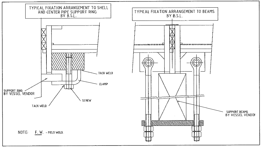
TRAY SUPPORT BEAM INSTALLATION
| Procedure | Hold points |
| – Preparation The support beams are laid down on trestles at ground. |
Cleanness (no rust). Number of support beams. |
| Main beam installation
During beam installation, Axens inspector must supervise the beam installation from inside the tower if possible. |
Rocking. Centering inside support ( delta max: 1 mm). Centering of the beam between the 2 supports (delta max: 5mm). Alignment: – beam upper face with center pipe support ring upper face (tolerance :-1; + 3 mm) |
| – Secondary beam installation
During beam installation, Axens inspector must supervise the beam installation from inside the tower if possible. |
Rocking Centering inside support ( delta max: l mm) and shim plates tack welded. Centering between the 2 supports ( delta max: 5mm with the shortest distance between beam angle and shell). Alignment: |
| – Axis tracing
Trace main beams axis only using a ruler with a paint marker. Using as reference, on each side of the center pipe, the middle of the length between the two longest secondary beams, mark up the center pipe and the shell for further vessel dimension measurement at 700 mm from the screen. |
Axis paint marking on Main beam axis, shell & center pipe. |
TRAY PANEL INSTALLATION
| Procedure | Hold points |
| – Preparation Panels are laid down on trestles at ground. Punch mark & screen status carefully inspected. Check the inside of the tray panels by removing the plastic cap, blow dry air or vacuum clean if necessary. At ground, all nozzles covered with plastic cap. Neoprene sheets taped on screen. |
Dry air in service in the adsorbers Panel conditions at ground Panel nozzle covers Gasket type |
| – Cleanliness During panel installation, avoid any sieve surface disturbing and ensure there is no foreign material |
Upper face of beams Upper face of support rings |
| – Lower panel screen Before positioning, each panel screen must be inspected carefully with a flash light ( damages done during handling) |
Panels 1A to 8B |
| – Gap between panels Install spacers for positioning and maintain the position with clamps. |
Gap between panels must be 15 mm max. |
| – Gap between panels and shell Maintain a minimum gap on shell side for the rope. |
Gap between panels and shell must be IO mm min. |
TRAY PANEL FASTENING
| Procedure | Hold points |
| – Clamps screwing Install at first the screw clamps to tight the trays with the annular support ring around the center pipe and the shell – Plate and forks joints installation Once clamps are in position use the plate and fork joint to finalize the tightness between trays and beams. |
Presence of fastening elements Tightness of fastening elements |
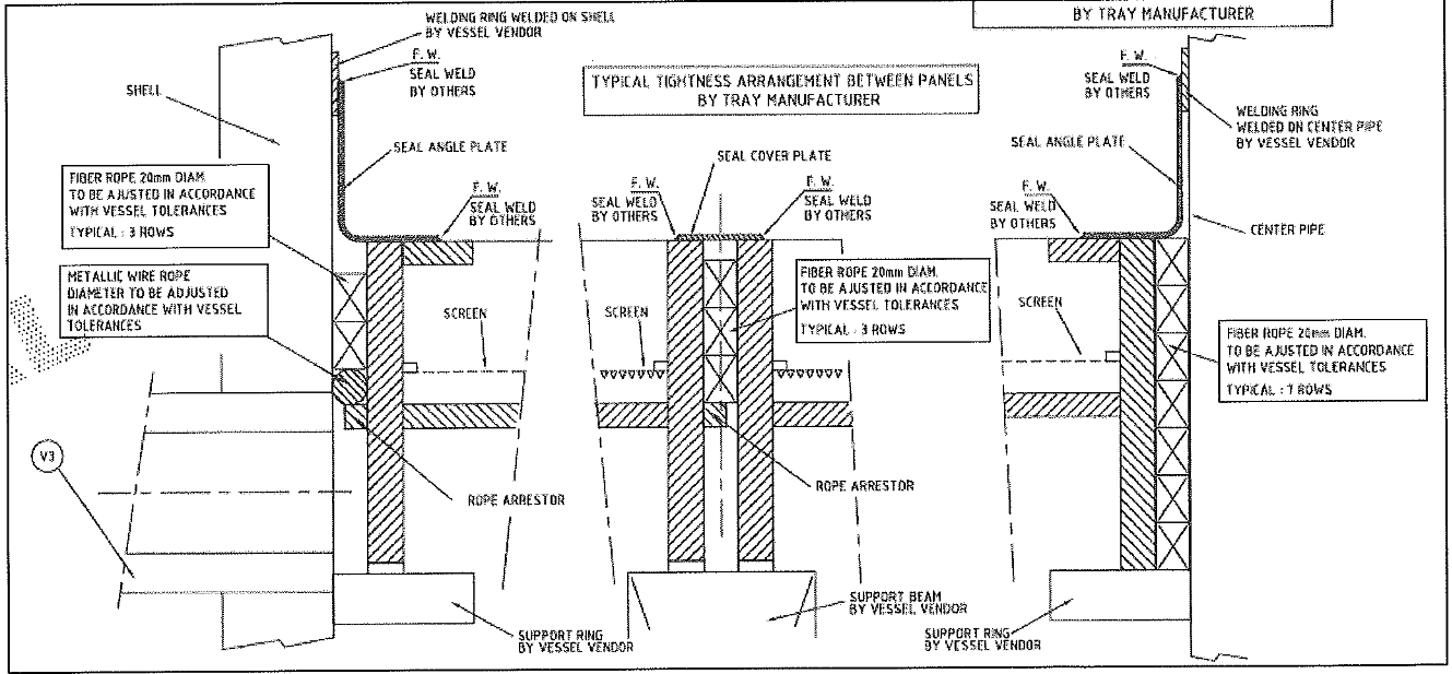
ROPE PACKING
| Procedure | Hold points |
| General remark: Because of the toleranxces regarding roundness of the shell, the diameter of the rope to be used shall be adjusted (30, 20, 8mm) according to the gap available especially between the panels and the shell. The rope packing shall be done smoothly to avoid damaging the rope. |
| – Wire rope installation Wire rope diameter is to be selected depending on the available gap between shell and rope arrestor. Wire rope is used locally in order to avoid any plugging of the bottom head vent during rope packing. |
Install wire rope around the bottom head vent nozzle. |
| – Rope packing general comments : Rope packing must be done following a specific sequence given by Axens. Use the recommended rope packing tools. – First row The first row must be packed carefully against the rope arrestor in order to prevent the rope going through it. – Rope packing Complete the rope filling up to the top of panel frames. – Last row of rope Last row of rope must be flush to upper edge of panel frame. |
First row of rope wrapping & status (clean and dry) & type & diameter No free space between panels Gap after rope packing: 15 mm Max between panels Last row of rope must be flush to upper edge of panel frame. |
| First row of rope wrapping & status (clean and dry) & type & diameter No free space between panels Gap after rope packing: 15 mm Max between panels Last row of rope must be flush to upper edge of panel frame. |
Cleanness Remaining Rope wrapping status |
LOWER TRAY SEALING: SEAL PLATE & SEAL ANGLE PLATE WELDING
| Procedure | Hold points |
| – Seal cover plate welding on panel frame Follow typical sequence of tack-welding: tackweld point pitch= 150 mm Then continuous welding to tight the tray |
Dye test |
| – Seal angle plate welding on center pipe and shell welding ring Follow typical sequence of tack-welding: tackweld point pitch= 150 mm Then continuous welding to tight the tray |
Dye test |
LOWER PIPING MANIFOLD INSTALLATION
| Procedure | Hold points |
| – Preparation Identify pipes to be assembled and pipes to be fitted before mounting. Remove all nozzle covers. Inspect lower manifold piping at ground. Store all big pieces of piping manifold inside the tower on bottom head. |
Piping condition ( cleanliness, rust free, dry). Dye check Welding quality |
| – Center pipe connection | Gasket type Bolting tightness |
| – Tray Cleaning/ scaffolding dismounting Remove scaffolding, vacuum clean all tray surface |
Cleanliness |
LOWER MANIFOLD PIPING I LOWER TRAY TESTS
| Procedure | Hold points |
| – Lower tray/ manifold piping mechanical / leak test Follow AXENS’s procedure |
EQUILIBRIUM DEVICE INSTALLATION
| Procedure | Hold points |
| – Preparation Clear out all tray surface and vacuum clean all dust on shell. Clean, brush rust if any on the flange. |
Piping condition ( cleanness, rust free, dry Flange cleanness |
| – Equilibrium device installation / bolting | Gasket type Gasket positioning Bolting tightness Bolting on lugs |
| -Bottom head flush inlet connection (2 in. ) | Piping assembly after tack welding. Dye check Welding quality Gasket type Gasket positioning Bolting tightness |
| -Sampling connection (3/4 in.) | Piping assembly after tack welding. Dye check Welding quality |
FINAL INSPECTION/ BOTTOM HEAD FINAL CLOSURE
| Procedure | Hold points |
| – Final inspection | Cleanliness Gaskets installation |
| – Bottom head manhole closure | Gasket position, type Tightness of bolting |
| – Pumparound nozzle closure | Temporary Gasket installation |
NEXT TRAY SUPPORT BEAM INSTALLATION
| Procedure | Hold points |
| – Preparation The support beams are laid down on trestles at ground. |
Cleanness (no rust) Number of support beams |
| Main beam installation During beam installation, Axens inspector must supervise the beam installation from inside the tower if possible. To check level, flatness of the upper surface and alignment use spirit levels (short and long). In case of beam rocking, shim plates of different thickness must be used and tack welded on support beam. Signed up on all checking points with a paint marker as following Axens marking procedure |
Rocking Centering inside support ( delta max: 1 mm) Centering of the beam between the 2 supports ( delta max: 5mm ) Alignment: |
| – Secondary beam installation During beam installation, Axens inspector must supervise the beam installation from inside the tower if possible. To check level and alignment use spirit levels. In case of beam rocking, shim plates of different thickness must be used and tack welded on support beam. Signed up on all checking points with a paint marker as following Axens marking procedure Follow the Axens sequence of installation |
Rocking Centering inside support ( delta max: 1 mm) and shim plates tack welded. Centering between the 2 supports (delta max: 5mm with the shortest distance between beam angle and shell). Alignment: – beam upper face with center pipe support ring upper face (tolerance :-1; +3 mm) – beam upper face with shell support ring upper face (tolerance: -1; +3 mm) |
| – Axis tracing Trace main beams axis only using a ruler with a paint marker. Using as reference, on each side of the center pipe, the middle of the length between the two longest secondary beams, mark up the center pipe and the shell for further vessel dimension measurement at 700 mm from the screen. |
Axis paint marking on Main beam axis, shell & center pipe. |
FIXED THERMOCOUPLE VERIFICATION ON BED 2, 6, 12, 14, 18, 24
| Procedure | Hold points |
| Check any damage on the thermowell Pack some rope in the nozzle to minimize dead volume |
Status of the thermowell Rope packing in the nozzle |
TRAY FINAL CLEANING
| Procedure | Hold points |
| – Preparation Remove the section of ladder present in the bed Remove all debris and tools. Vacuum clean the neoprene sheets before removal. Remove all neoprene sheets and vacuum clean the screen. Wear shoes protection before starting the tray final cleaning to avoid damaging the screen |
Shoes protection to be worn all the time Bed free of ladder |
TRAY FINAL INSPECTION
Items for inspection : Laser meter, ruler (3m), pen, wrench XX, spirit levels (short & long), flash light, Axens tray doc., small knife
| Procedure | Hold points |
| – Adsorber conditions Dry air must be blown to ensure a dry atmosphere before sieve loading |
Dry air in service Access to bed during loading |
| – Ladder | Bed free of ladder |
| – Screen status & slot spacing | Slot spacing checking with feeler gauge |
| – Rope packing | Rope packed everywhere |
| – Seal plates | Position Welding |
| – Beam conditions Walk on it to detect any rocking |
Rocking Level Axis marking (beam axis) |
| – bottom head piping Look for any uncompleted work, absence of gasket… (and presence of the additionnal piping needed as V3 complement) |
Bolting ( checked with a wrench) Gasket type |
| – Cleanness Look for remaining tools, dye stains, welding stains. In case of dust or dirt, ask for more cleaning (vacuum cleaner). |
Shell / center pipe Upper part of beams Support Ring on center-pipe / shell Screen surface |
| – Thermocouple | Position |
| – Collect data for volume calculation | Bed diameter measurement Height measurement |
BEFORE LEAVING THE BED CHECK THAT ALL TOOLS USED FOR INSPECTION HA VE BEEN COLLECTED