An internal combustion engine is a type of heat engine that generates power by burning fuel inside a combustion chamber. This combustion process produces high-pressure gases that expand and exert force on pistons or turbine blades, resulting in mechanical work. Internal combustion engines are commonly used in vehicles, such as cars, trucks, motorcycles, and aircraft, as well as in various stationary applications like power generators and pumps. They operate on the principles of thermodynamics, converting the chemical energy stored in fuel into mechanical energy for propulsion or other useful work.
What is Internal Combustion Engine?
The internal combustion engine is a marvel of engineering, serving as a versatile power source in various applications. One of the primary categorizations of internal combustion engines is based on their fundamental design. Reciprocating engines, the most common type, rely on a cylinder-piston arrangement to generate power through controlled combustion. In contrast, rotary engines utilize a turbine setup for power generation, offering distinct advantages in certain applications.
Fuel type is another crucial aspect defining the classification of internal combustion engines. Petrol engines, commonly found in automobiles, operate on gasoline fuel, while diesel engines utilize diesel fuel, known for its efficiency and torque. Gas engines are designed to run on compressed natural gas (CNG), liquefied petroleum gas (LPG), or other gases, offering environmental and economic benefits. Additionally, alcohol engines, powered by ethanol, methanol, or similar substances, represent an alternative fuel option with potential environmental advantages.
The number of strokes per cycle is a defining characteristic of internal combustion engines. Four-stroke engines, prevalent in automotive and industrial applications, undergo intake, compression, power, and exhaust strokes in each combustion cycle. On the other hand, two-stroke engines complete the combustion cycle in just two strokes, offering simplicity and compactness but often at the expense of efficiency.
Ignition method is another critical factor in engine classification. Spark ignition engines rely on a spark plug to ignite the fuel-air mixture, commonly found in gasoline-powered vehicles. Compression ignition engines, prevalent in diesel engines, ignite the fuel by compressing the air within the cylinder, leading to spontaneous combustion. Hot spot ignition engines use a heated spot to initiate combustion, offering an alternative method suitable for specific applications.
The working cycle of an engine determines its efficiency and performance characteristics. Otto cycle engines, following a constant-volume cycle, are common in gasoline-powered vehicles, offering a balance of power and fuel efficiency. Diesel cycle engines, operating on a constant-pressure cycle, are renowned for their torque and fuel economy, making them ideal for heavy-duty applications. Dual combustion cycle engines combine elements of both Otto and diesel cycles, offering a compromise between power and efficiency.
Fuel supply and mixture preparation methods vary among internal combustion engines. Carbureted engines rely on a carburetor to supply fuel and air mixture to the combustion chamber, whereas injection-type engines inject fuel directly into the cylinder or intake manifold, offering precise control over fuel delivery and combustion.
In addition to these factors, the number of cylinders, cooling method, engine speed, cylinder arrangement, valve or port design, governing method, and application play significant roles in classifying internal combustion engines, each contributing to the engine’s performance, efficiency, and suitability for specific tasks.
Comparison between external combustion engine and internal combustion engine
| Feature | External Combustion Engine | Internal Combustion Engine |
|---|---|---|
| Combustion Location | Combustion of air-fuel mixture occurs outside the engine cylinder | Combustion of air-fuel mixture occurs inside the cylinder |
| Noise Level | Operates smoothly and silently due to external combustion | Operates noisily |
| Weight and Bulk | Heavier and bulkier due to auxiliary apparatus like boilers | Lighter and more compact due to absence of external apparatus |
| Working Pressure and Temperature | Lower pressure and temperature, uses ordinary alloys | Higher pressure and temperature, requires special alloys |
| Fuel Type | Can use cheaper fuels, including solid fuels | Requires higher-grade fuels with proper filtration |
| Efficiency | Lower efficiency (about 15-20%) | Higher efficiency (about 35-40%) |
| Water Requirement | Higher requirement for cooling system | Lesser requirement for cooling system |
| Starting Torque | – | High starting torque |
| Self-Starting | Not self-starting | Self-starting |
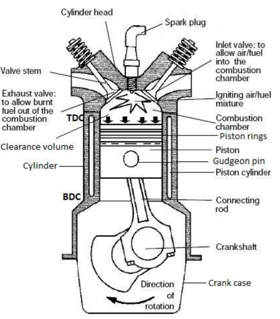
Components of Reciprocating Internal Combustion Engine
The reciprocating internal combustion (IC) engine comprises several key components essential for its operation:
- Cylinder: The main chamber where the piston moves back and forth. It must endure high pressure and temperature, often made from cast iron for standard engines and steel or aluminum alloys for heavy-duty engines. In multi-cylinder engines, cylinders are cast together in a single block known as the cylinder block.
- Cylinder Head: Covers the top end of the cylinder and houses components like inlet and exhaust valves, spark plugs, or injectors. A gasket seals the cylinder head to maintain an airtight joint with the cylinder.
- Piston: Transfers the force generated by the combustion of fuel to the connecting rod. Typically made from aluminum alloy for its heat conductivity and strength at high temperatures.
- Piston Rings: Situated in grooves around the piston’s outer surface, these rings, made of steel alloys, maintain elasticity even under high temperatures. Compression rings ensure an airtight seal, while oil rings prevent oil leakage into the cylinder.
- Connecting Rod: Converts the piston’s reciprocating motion into the crankshaft’s rotary motion during the working stroke. It connects the piston to the crankshaft via a gudgeon pin and crank pin, often constructed from special steel or aluminum alloys.
- Crankshaft: Transforms the reciprocating motion of the piston into rotary motion with the assistance of the connecting rod. Manufactured from special steel alloys, it features an eccentric portion known as the crank.
- Crankcase: Houses the cylinder and crankshaft, also serving as an oil sump for lubrication purposes.
- Flywheel: A large wheel mounted on the crankshaft to maintain its speed constant. It stores excess energy during the power stroke, releasing it during other strokes to ensure smooth operation.
Terminology used in Internal Combustion engine:
Here’s a breakdown of the key terminology used in internal combustion (IC) engines:
- Cylinder Bore (D): The nominal inner diameter of the working cylinder.
- Piston Area (A): The area of the circle with a diameter equal to the cylinder bore.
- Stroke (L): The nominal distance traveled by the piston between two successive reversals of its motion direction.
- Dead Centre: The position of the piston and connected moving parts when the piston’s motion direction is reversed. Two main dead centers are:
- (a) Bottom Dead Centre (BDC): When the piston is closest to the crankshaft.
- (b) Top Dead Centre (TDC): When the piston is farthest from the crankshaft.
- Displacement Volume or Swept Volume (Vs): The nominal volume generated by the piston when it moves from one dead center to the next. Calculated as Vs = A × L.
- Clearance Volume (Vc): The nominal volume of the space on the combustion side of the piston at top dead center.
- Cylinder Volume (V): The total volume of the cylinder, given as the sum of displacement volume and clearance volume (V = Vs + Vc).
- Compression Ratio (r): r=Vs/Vc
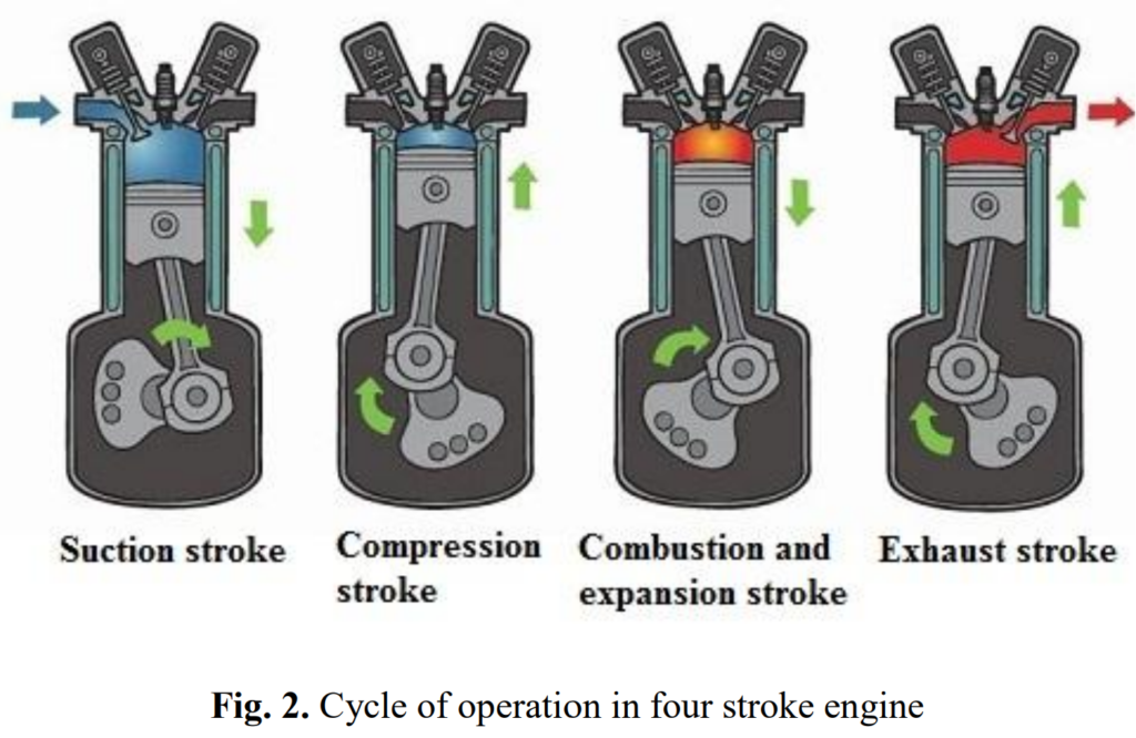
Four stroke engine:
A four-stroke engine completes its cycle of operation in four strokes of the piston or two revolutions of the crankshaft. Here’s a breakdown of each stroke:
- Suction Stroke:
- During this stroke, the suction valve opens while the exhaust valve remains closed.
- A mixture of fresh air and fuel is drawn into the cylinder as the piston moves from top dead center (TDC) to bottom dead center (BDC).
- The vacuum pressure created by the downward movement of the piston facilitates the intake of the air-fuel mixture.
- Compression Stroke:
- In this stroke, both the suction and exhaust valves are closed.
- The piston moves back up from BDC to TDC, compressing the fresh charge into the clearance volume.
- The compressed mixture is ignited by a spark plug for combustion, leading to an increase in pressure and temperature within the cylinder.
- Expansion Stroke:
- During the expansion stroke, both valves remain closed.
- The high-pressure gases resulting from the combustion force the piston back towards BDC, generating power at the crankshaft.
- Exhaust Stroke:
- In this stroke, the exhaust valve opens while the suction valve remains closed.
- The piston moves from BDC to TDC, expelling the burned gases out of the cylinder.
The sequence of these strokes completes one cycle of operation for the four-stroke engine, as illustrated in Figure 2.
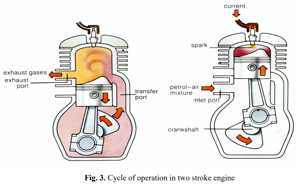
Two stroke engine:
A two-stroke engine operates with a different cycle compared to a four-stroke engine. Here’s an overview of its operation:
- No Separate Suction and Exhaust Strokes:
- Unlike a four-stroke engine, a two-stroke engine does not have dedicated suction and exhaust strokes. Instead, these operations occur simultaneously during each revolution of the piston.
- Suction Mechanism:
- Suction of the air-fuel mixture is achieved either by air compressed in the crankcase or by a separate blower mechanism.
- Exhaust Operation:
- As the piston moves upward, it compresses the air-fuel mixture in the combustion chamber.
- Simultaneously, the burned gases from the previous cycle are expelled through exhaust ports.
- Transfer Port:
- A transfer port is present in the cylinder wall to supply the fresh air-fuel mixture into the combustion chamber.
- This transfer of the mixture occurs while the piston is at the bottom of its stroke.
Figure 3 illustrates the operation of a two-stroke engine, showcasing its simplified cycle compared to a four-stroke engine.
Comparison of Four-stroke and two-stroke engine:
Here’s a comparison between four-stroke and two-stroke engines:
| Characteristic | Four-Stroke Engine | Two-Stroke Engine |
|---|---|---|
| 1. Cycle | Four strokes of the piston and two revolutions of crankshaft | Two strokes of the piston and one revolution of crankshaft |
| 2. Power Stroke | One power stroke in every two revolutions of crankshaft | One power stroke in each revolution of crankshaft |
| 3. Flywheel | Heavier flywheel due to non-uniform turning movement | Lighter flywheel due to more uniform turning movement |
| 4. Power Output | Power produced is less | Theoretically, power produced is twice than the four-stroke engine for the same size |
| 5. Size | Heavy and bulky | Light and compact |
| 6. Cooling/Lubrication | Lesser cooling and lubrication requirements | Greater cooling and lubrication requirements |
| 7. Wear and Tear | Lesser rate of wear and tear | Higher rate of wear and tear |
| 8. Valve Mechanism | Contains valve and valve mechanism | Contains ports arrangement |
| 9. Initial Cost | Higher initial cost | Cheaper initial cost |
| 10. Volumetric Efficiency | Volumetric efficiency is more due to greater time of induction | Volumetric efficiency less due to lesser time of induction |
| 11. Thermal Efficiency | Thermal efficiency is high and also part load efficiency is better | Thermal efficiency is low, part load efficiency is lesser |
| 12. Applications | Used where efficiency is important (e.g., cars, buses, trucks, tractors, industrial engines, airplanes, power generation) | Used where low cost, compactness, and light weight are important (e.g., lawn mowers, scooters, motorcycles, mopeds, propulsion ships) |
Comparison of SI and CI engine:
Here’s a comparison between SI (Spark Ignition) and CI (Compression Ignition) engines:
| Characteristic | SI Engine | CI Engine |
|---|---|---|
| Working Cycle | Otto cycle | Diesel cycle |
| Fuel | Petrol or gasoline or high octane fuel | Diesel or high cetane fuel |
| Self-Ignition Temperature | High | Low |
| Fuel Intake | Fuel and air introduced as a gaseous mixture in the suction stroke | Fuel is injected directly into the combustion chamber at high pressure at the end of compression stroke |
| Fuel Supply | Carburettor used to provide the mixture | Injector and high-pressure pump used to supply fuel. Quantity of fuel regulated in the pump |
| Ignition System | Use of spark plug for ignition system | Self-ignition by the compression of air, which increases the temperature required for combustion |
| Compression Ratio | 6 to 10.5 | 14 to 22 |
| Maximum RPM | Higher maximum RPM due to lower weight | Lower maximum RPM |
| Efficiency | Maximum efficiency lower due to lower compression ratio | Higher maximum efficiency due to higher compression ratio |
| Weight | Lighter | Heavier due to higher pressures |
Valve Timing Diagram of Internal Combustion Engine:
In an internal combustion engine, the precise timing of when the inlet and outlet valves open and close in relation to the position of the piston and crankshaft is crucial for optimal performance. This timing, represented graphically, is called the valve timing diagram, typically measured in degrees of crank angle. While a theoretical valve timing diagram provides an idealized representation, the actual valve timing diagram differs due to mechanical and dynamic factors.
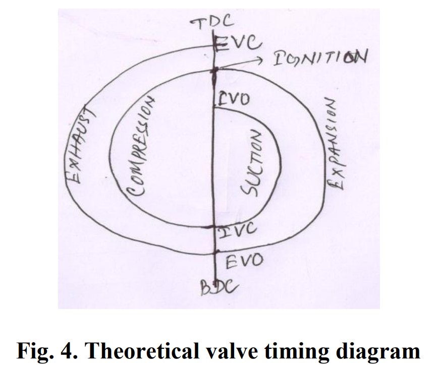
Figure 4 illustrates the theoretical valve timing diagram, outlining the ideal opening and closing timings of the valves relative to the piston and crankshaft positions. However, in real-world scenarios, mechanical constraints and dynamic engine behavior lead to deviations from this ideal diagram. For both low-speed and high-speed four-stroke engines, the actual valve timing diagram is depicted in Figure 4, showcasing the practical valve operation timings.
Opening and closing of inlet valve
In the operation of an internal combustion engine, the timing of the inlet valve’s opening and closing plays a critical role in engine performance:
- Opening of Inlet Valve: The inlet valve typically opens between 12 to 30 degrees of crank angle (CA) before the top dead center (TDC) position. This early opening facilitates smoother and quieter engine operation, especially at high speeds. Additionally, it enhances the engine’s volumetric efficiency by allowing more air-fuel mixture to enter the cylinder during the intake stroke.
- Closing of Inlet Valve: The inlet valve closes approximately 10 to 60 degrees of CA after the TDC position. This delayed closing is due to the inertia effect, where the momentum of the incoming fresh charge helps fill the cylinder even after the piston begins its upward stroke. This ensures maximum intake of the air-fuel mixture into the combustion chamber.
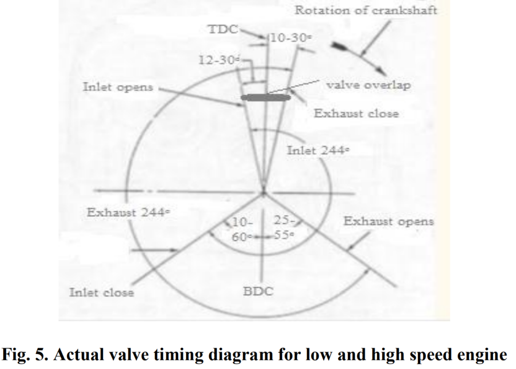
Figure 5 illustrates the actual valve timing diagram for both low and high-speed engines, showcasing the precise timings of inlet valve operation relative to the piston and crankshaft positions.
Opening and closing of exhaust valve
In the operation of an internal combustion engine, the timing of the exhaust valve’s opening and closing is crucial for efficient expulsion of burnt gases:
- Opening of Exhaust Valve: The exhaust valve typically opens between 25 to 55 degrees of crank angle (CA) before the bottom dead center (BDC). This early opening reduces the work required to expel the burnt gases from the cylinder during the exhaust stroke. Towards the end of the expansion stroke, when the pressure inside the chamber is still high, opening the exhaust valve allows for smoother gas expulsion.
- Closing of Exhaust Valve: The exhaust valve closes approximately 10 to 30 degrees of CA after the top dead center (TDC). This delayed closing prevents the compression of burnt gases in the next cycle. By allowing the kinetic energy of the burnt gas to aid in its expulsion, this timing also maximizes the exhausting of the gas and contributes to increased volumetric efficiency.
It’s important to note that for low-speed and high-speed engines, the lower and upper values, respectively, are utilized to optimize engine performance.
These timings ensure efficient operation of the engine, minimizing energy losses and maximizing power output.
Valve overlap
Valve overlap refers to the period during the engine’s operation when both the intake and exhaust valves are simultaneously open. This timing is strategically planned to optimize the engine’s performance:
- Intake Valve Opening: The intake valve is opened before the exhaust gases have entirely exited the cylinder. This timing allows the high-velocity exhaust gases to create a vacuum effect, aiding in the efficient intake of the fresh air-fuel mixture into the cylinder during the intake stroke.
- Exhaust Valve Closing: Engine designers aim to close the exhaust valve just as the fresh charge from the intake valve reaches it. This precise timing prevents any loss of fresh charge or the presence of unscavenged exhaust gas in the combustion chamber, ensuring optimal combustion conditions.
By carefully managing the timing of valve overlap, engine designers can maximize the engine’s efficiency and power output while minimizing emissions and energy losses.
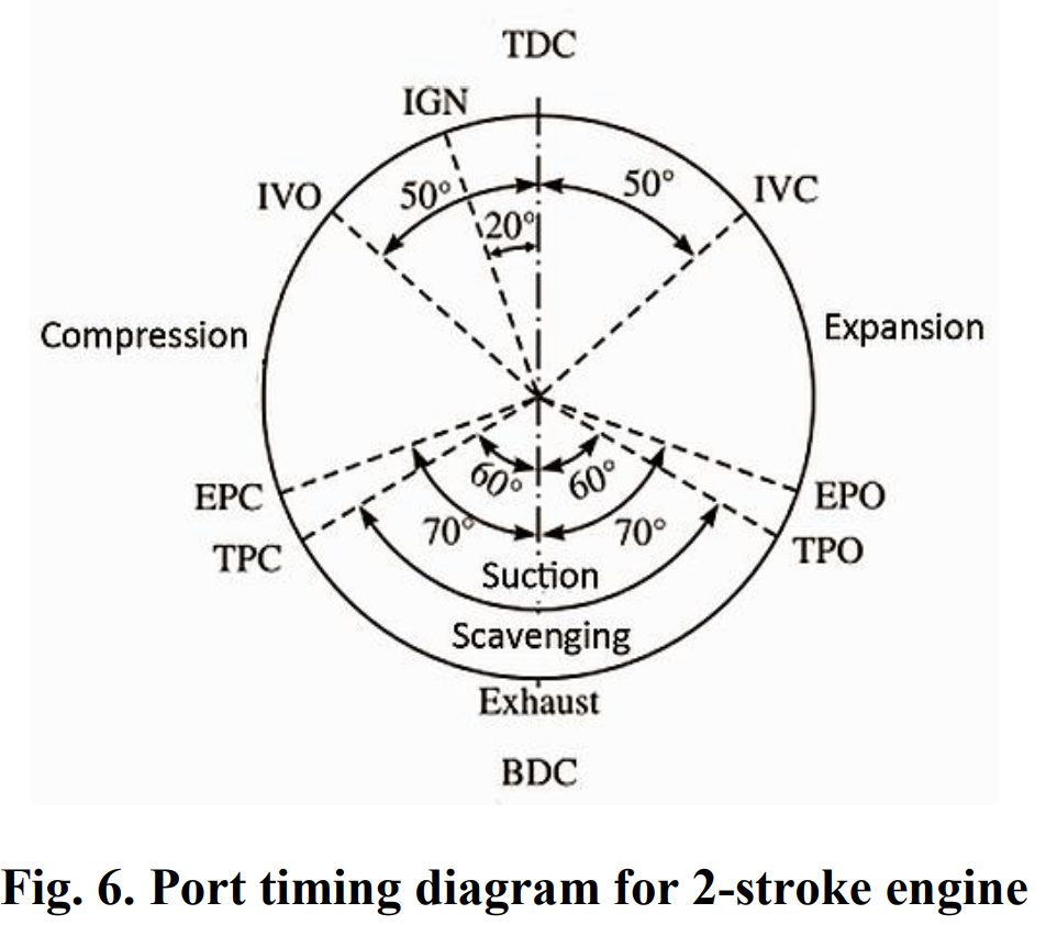
Port Timing Diagram of Internal Combustion Engine:
A port timing diagram is specifically drawn for 2-stroke engines and does not involve any valve arrangement. Instead, it focuses on the timing of the engine’s ports, which are openings in the cylinder wall that control the flow of air-fuel mixture and exhaust gases. Typically, a 2-stroke engine has three ports: the inlet port, the transfer port, and the exhaust port.
The port timing diagram illustrates the opening and closing of these ports relative to the position of the piston and the crankshaft. This timing is critical for ensuring efficient scavenging of exhaust gases, intake of fresh air-fuel mixture, and compression of the mixture within the cylinder.
Figure 6 depicts a typical port timing diagram for a 2-stroke engine, showing the timing events for the opening and closing of the inlet, transfer, and exhaust ports throughout the engine’s cycle of operation. Understanding and optimizing port timing is essential for achieving optimal performance and efficiency in 2-stroke engine designs.