This article is about Instrumentation, Box and Barrier Installation and Commissioning for Intrinsically Safe Circuits.
Intrinsically Safe Circuits Instrumentation, Box and Barrier Installation
General Requirements for Intrinsic Safe Circuits
For Class I, Zone 0 areas, all instruments should be intrinsic safety as protection method.
For equipment installation, Project Control drawings to be followed for intrinsically safe apparatus, associated apparatus and other equipments.
Keep in Mind: A simple Instrument that do not interconnect intrinsically safe circuits.
For Class I, Zone 1, 2 electrical hazardous areas, we can use intrinsically safe circuits only when there is no other method of protections.
For Interconnecting wiring:
Intrinsically safe circuits conductor or wires shall not be installed with other power or non I.S conductors cable tray, raceway.
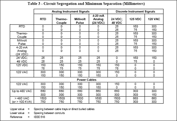
Do not install intrinsically safe circuits interconnecting cables near to heavy current power cables and overhead power distribution lines. Check this document SAES-J-902 for minimum spacing requirements between parallel cable runs of different signal types. (Attachment 1)
Intrinsically Safe Circuits Installation Requirements:
Installation, Field Instrument:
The ingress safe protection NEMA 4X or IP 65 to be provided to seal intrinsically safe instrument enclosure.
Interconnecting wiring:
Separate or dedicated junction boxes for intrinsically safe field termination to be installed to provide positive separation of intrinsically safe from non-intrinsically safe wiring.
All intrinsically safe instrumentation loops shall be installed or routed to common field termination box / cabinet.
Field termination junction box shall be used as junction point from individual pair/triad to a multi-pair/triad cable for any maintenance purpose.
I.S and Non I.S signals shall not combine in multi core cables.
As per NEMA Standard 250, Field termination junction boxes shall be NEMA type 4X or IP65.
As per NEC National Electric Code NFPA 70, SAES-B-008, and SAES-O-126, Cable shall be sealed to prevent the passage of gas and vapors.
Cable trays, Conduits, OR Direct buried cables methods can be used to route I.S System Multi-pair/triad cables from field junction boxes to process control room or process interface buildings (PIB).
Termination:
Dedicated marshalling cabinets shall be used for intrinsically safe system wiring termination or can be used some compartment of marshalling cabinet. Cable entries of non-intrinsically safe and intrinsically safe wiring shall be completely separate and opposite.
Marshalling cabinets for I.S System with related equipment shall be within process control rooms, or outside air conditions shelters etc.
Interconnecting wiring, Signal Segregation:
Instrument signals 4-20 mA, Thermocouples and digital signal shall be separated by dedicated, intrinsically safe junction boxes by following standard practices. And signal segregation shall be keep up to marshalling cabinets in control room.
50 mm (2 inches) gap shall keep between intrinsically safe and non I.S Cable within marshalling cabinet or cabinet that contains associated apparatus.
The I.S. cables from the field instrument shall be terminated on the “hazardous area” terminations of the associated apparatus and shall be secured or tie-wrapped separately from the non-intrinsically safe cables terminated on the opposite end “safe area” terminals of the associated apparatus.
Grounding and Identification Requirements
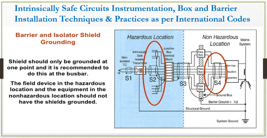
Intrinsically safe system related apparatus, cable shields and enclosures shall be grounded.
I.S Spare wires shall be terminated at terminal blocks and grounded to I.S ground bus. Insulated shall be provided for unused wires at field area side (Hazardous areas).
¼ inch (6 mm) is minimum gap to be maintained between two different intrinsically safe circuits terminals. And 1/8 inch (3 mm) is minimum gap to be maintained between I.S Circuits and any grounded point or metals.
Intrinsic safety grounding bus of Control cabinets having I.S associated apparatus shall be connected to overall plant grounding grid. The minimum grounding cable size should be #4 AWG and must be dedicated, redundant and insulated copper cables. Grounding Conductor insulation color is green with blue tracer make difference between intrinsically safe grounding conductors and other safety grounding cables / conductors.
Outer insulating sheath shall be used to cover to cover screen and shields. Screen/Shields used for I.S Cable shall be grounded at intrinsic safety point in field junction box or control room and shall be insulated at hazardous area field side.
Where screened multipair / multitriad cables interconnect within field junction boxes with individual screened pair/triad cables, insulated terminals shall be provided for the ongoing continuity of the screens/shields.
1 ohm (not more) resistance is required between plant grounding system (where incoming electrical supply neutral is grounded) and intrinsic safety barrier ground in case of zener diode barriers.
To ground all metal enclosures related to intrinsically safe circuits with plant grounding system shall use minimum of #4 AWG Green insulation copper wire.
If you are using protective armor cable, it must be grounded with plant grounding system at field junction box.
Identification:
Identification shall be done for all intrinsically safe system circuits or devices. I.S related all cable tray, junction boxes, cabinets, conduits, cables, instrument housings must be labelled or identified. Visible labelling shall be done after installation. 8 meters (25 feet) label or identification tag shall be installed for conduits, cable tray and interconnecting cables.
For intrinsically safe wiring, light blue color shall be used. Use of Blue outer jacket for intrinsically safe interconnecting cables is common practice. You can use blue sleeves also over I.S Wiring jacket for all termination point to show as intrinsic safe wiring.
Terminals:
To prevent unintentional interference with other circuits during maintenance, servicing and testing, I.S Circuits to be identified at junction boxes and field terminals.
Testing
An I.S. system may be tested and maintained under live (working) conditions provided the portable test equipment used has been certified and approved as intrinsically safe for the particular atmospheric hazard. Otherwise, a hot work permit shall be issued.
Only safety barriers/isolators of the same type, make, or catalog number shall be used to replace defective safety barriers/isolators.
Only devices of the same make, type, and catalog number or replacement recommended by the manufacturer shall be used to replace any device in the system.
In I.S Loop, if any changes, additions, deletions of any intrinsic safe components within a loop, shall be noted down at the operating facility in the ILD drawings.
International Codes and Standards
- Foundation Fieldbus Implementation
- Instrument Cable Installation, Termination, Identification and Commissioning
- ISA-RP 12.2.02 -1996 Recommendations for the Preparation , Content and Orga. Of Intrinsic Safety Control Drawings.
- SAES-J-902 – Electrical Systems for Instrumentation.
- SAES-J-903 – Intrinsically Safe System.
- NFPA 70 – National Electrical Code.
1. Attachment 1: SAES-J-902, Table 3, 4 & 5; Circuit Segregation and Minimum Separation (Millimeters)

