Introduction to Loop Checking of Instrumentation – Loop Checking Preparation
-
- Instrumentation
- Types of loops
- Types of signals
- DCS
- PLC & ESD system
- Alarms
- Generally used terms in instrumentation legends
- Temp vs mv tables for all kinds of thermocouples
Test equipment & tools
-
- Tools required for loop checking work
- Test Equipments required for loop checking
Loop check procedures
Steps & procedures of loop checking
- Familiarization of loop diagram & Loop package
- Process simulation methods during loop checking
- Loop checking of pressure transmitter (Local indicator)
- Loop checking of differential pressure / flow transmitters
- Loop checking of level transmitter (DP type) local indicator
- Loop checking of level transmitter displacer type local in
- Loop checking of temperature transmitter (RTD type)
- Loop checking of temperature transmitter (T/C type)
- Loop checking of control valves (Characteristics check & confirm)
- Loop checking of ON/OFF valves
- Loop checking of special instruments
- Loop checking of pressure switches
- Loop check arrangements figures
- Conversation tables of pressure
- Temp vs resistance tab
- Instrumentation
The instrumentation is branch of engineering which deals with the measuring, manipulation and controlling of process variable like pressure, flow, temperature, level etc.
- Types of Loops
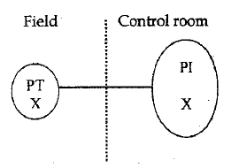
- Open Loop
Open Loop is which contains only primary measuring system and indicator. ·
For e.g. A Pressure transmitter is measuring the pressure of a gas line and DCS is indicating the pressure in control room for the operator alert
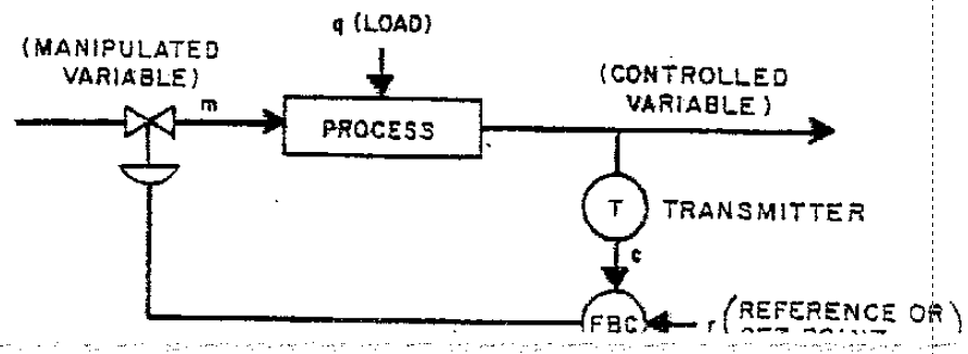
- Closed Loop
Closed loop, which contains primary measuring system controller and final control element
for E.g. A Pressure transmitter “X” is measuring the pressure of a gas line and a controller in DCS is monitoring and controlling the pressure by operating final control element i.e. control valves
Closed loop can be operated in 3 modes
- Manual modes
- Auto modes
- Cascade modes
Manual Mode
In this mode, the controller will not respond to the process variable changes. The controller will give the output, which is fed by the operator to control valves.
This mode is using for loop checking of control valves.
Auto Mode
In this mode the controller is automatically controlling the process, by comparing the measured variable to the set point signal entered to the controller and giving out put signal to final the control element to maintain the process variable constant at desired value.
Cascade Mode
Cascade mode consists of two or more controller and the output of one-controller positions the set point of another controller. This is generally used to control main process variable by controlling another variable, which can cause charges in the main variable.
- Types of Signal
- Analog Signal
(A.1) Analog Input (AI)
(A.2) Analog Input (AO)
- Digital Signal
(B.1) Digital Input (DI) (B.2) Digital Output (DO)
Analog Signal
The signal which it’s amplitude varies with time. i.e signal which consists of different states. Analog signal can be used for measurement purposes.
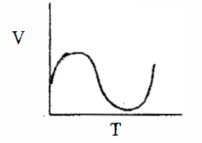
4-20mA output of a transmitters is an example of Analog input signal.
4-20mA from DCS/PLC to any control valve is an example of Analog output signal
Analog Input
The output of transmitter 4-20 mA
The output of RTD- resistance varies with temperature.
The output of thermocouple MV which varies with the temperature
Analog Output
The output from the controller which varies from 4mA to 20mA to the final control element is the analog output.
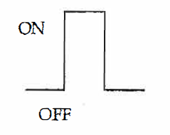
Digital Signal
The signal, which has only two states either ON or OFF Example. Any switches
Digital Input
The signal from any kind of switches like pressure switch, level switches etc, which has only two stages ON or OFF to the control system is digital input.
Digital Output
The signal from the control device which has two stages either ON or OFF to any control elements or indicating device is digital output.
The output for solenoid valve or lamps are the example for digital output.
- DCS (Distributed Control System)
Distributed control system is used for continuous process monitoring & control in a process plant The DCS has its central processing unit, input and output units, History modules, communication gateways etc. DCS has operator’s access through operating consoles in central control room.
- PLC (Programmable Logic Controller)
Programmable Logic Controller is used to maintain sequence control for a process, they are mainly used for the emergency shut down (ESD) purpose for the plant.
The PLC can also receive analog input and digital inputs as well as provide analog output and digital output.
- Alarms
The alarms are enabled to alert the operator prior to any abnormal condition occurs.
Mainly alarms are classified as below.
- High Alarm (H)
- High High Alarm (HH}
- Low Alarm (L)
- Low low Alarm (LL)
High and low alarms are called pre alarms and high, high and low, low are for trip. They are discriminated in DCS by colour changes. Normally pre alarms are in yellow colour and trip alarms are in red colour.
In addition to the Visual alarms audible alarms are also used to alert the operator when he is busy with any other work.
- Generally used terms in instrumentation
- I/ 0 (input/ output)
The interface between peripheral equipment and the control system.
- Response
Reaction to a forcing function applied to the input. The variation in output as a result of changes in input.
- Software
The collection of programs and routines associated with a computer.
- Hardware
Physical equipment, i.e. mechanical, magnetic, electrical as electronics devices, which we can touch with our finger.
- Instrument
In process instrumentation and control, this term is used to describe any device that performs a measuring or controlling function.
- Set point
The instruction given to the automatic controller for determining the point at which the controlled variable hopefully to stabilize.
- Transducer
A device that converts information of one physical form to another physical type in it’s output (e.g a thermo couple converts temperature to milli voltage (mV).
- value
The level of signal being measured and controlled.
- Loop
A signal path
- Final control element
Component of a control system which directly regulates the flow of energy or material to the process.
- Accuracy
Conformity to an indicated, standard, or true value, usually expressed as a percentage (of span, reading or upper range value) deviation from the indicated, standard or true value. e.g± 0.5% , ±1%
- Span
The difference between the low range value and the high range value is called span.
- 4-20mA, the span is 20-4=16
(b) 0 – 2500 mm H20 Span = 2500 – 0 = 2500
- Legends used in instrumentation
AI Analog Input
AO Analog Output
DI Digital Input
DO Digital Output
V Voltage
MV Milli Volt.
A Ampere
mA Milli Ampere
PV Process Variable
SP Set Point
I/0 Input Output
F&G Fire &Gas
PT Pressure Transmitter
FT Flow Transmitter
LT Level Transmitter
TI Temperature Transmitter
AT Analyzer Transmitter
T/C Thermo Couple
RTD Resistance Temperature Detector
(PV Pressure Control Valve
LV Level Control Valve
TV Temperature Control valve
FV Flow Control Valve
xv On/Off Valve
AFO Air Failure Open
AFC Air Failure Oose
AFL Air Failure Lock
DCS Distributed Control System
PLC Programmable Logic Controller
SCADA – Supervisory Control and Data Acquisition
- TEST EQUIPMENT AND TOOLS
- Tools required for instrumentation work/ Loop checking
- Screw driver set
- Spanner Set (Open-end & ring)
- Box Spanner Set
- Adjustable Spanners (Screw spanners)
- Cutting Plier
- Nose pliers
- Terminal Connector
- Measuring Tape
- Vernier Caliper (Optional)
- Test equipment required for Loop checking
- Multimeter
- ma Simulator
- mv Simulator
- Decade resistance box (DRB)
- Temperature Calibrator/ Portable calibrator (eg Druck)
- Pressure Calibrator
- HART Communicator
- Nitrogen cylinder with Pressure regulator
LOOP CHECK PROCEDURE
- Steps & procedures of loop checking
Loop checking is the process to confirm the signal continuity from primary instrument (transmitters, switches) to DCS or PLC system and from DCS or PLC to the final control elements such as control valves, dampers ON/OFF valves, motor operated valves etc.
- Loop folder (packages) contents
Loop Packages means a file folder consists of
- Instrument Loop diagram (ILD) (See attachment)
- Piping & instrument diagram (P&ID) (See attachment)
- Instrument Data Sheet (See attachment)
- Instrument Calibration report (optiooal) (See attachment)
- Loop checking recording form (See attachment)
- Inspection checklist. (See attachment)
First step to loop checking
- Check and confirm the wiring is correct according to ILD
- Make sure no loose connections are present in the loop wiring
- Close knife switch and check voltage across the terminals
- Check the range in DCS/PLC whether the instrument calibration range in data sheet as in instrument configuration. The configuration can be checked by connecting a field communicator and verify.
- Use communication device to contact to CCR panel operator and check the readings @ 0% input. Then simulate the input 25%, 50%, 75% & 100% and confirm the indication in DCS are correct.
- Panel operation’s responsibility is to check and record the values in ITD forms also the alarm setting and response are correct respectively.
- If any instrument loops are not working then the corresponding loop package to be kept in separate place for the trouble shooting purpose.
- The trouble-shooting group consists of a team of talented technicians, to check and verify each and every point in the loop to find the discrepancies and
- The loops, which have completed troubleshooting, will hand over to loop checking team for final loop
Process simulation methods during loop checking
For pressure transmitter we can use DRUCK pressure calibrator. To simulate the actual process.
For DP/ flow level transmitter we can use DRUCK low range pressure calibrator.
For Displacer level transmitter simulation shall be done by filling the water and compensate the specify gravity of process fluid. Sect fig. For loop check arrangement drawing in sec.
For vibration signal we can use TK3 Bentley Nevada calibration to simulate vibration & axial displacement
For gas detector portable calibration cylinder can connect according to service and check the action in F&G system/ mimic panel.
- Loop checking of Pressure transmitter
Oose the isolation valve in manifold and open drain valve then connect the portable pressure calibrator to the drain port then without applying pressure
Check the reading in CCR by communicating with the panel operation.
li zero is correct, the apply 25%, 50%, 75% & 100% and record the readings in DCS/PLC accordingly
- Loop checking of Differential Pressure Flow Transmitter
Close the HP & LP isolation valves i the k way manifolds and then open the Hp & LP side drain valves.
Then check the zero is DCS/PLC in control room if zero is ok connect
the pressure calibrator on the Hp side of the transmitter then open the LP side to atmosphere.
Start applying 25%, 50%, 75% & 100% and record the values in
DCS/PLC accordingly.
But all the DP fl.ow transmitter are giving out put in square root value. The extraction ca be done in DCS so to check the reading of FT in 25% 50% or 75% simulation of differential pressure to be done in square root value.
Refer figure 1. for more detail about the arrangement
The simulation can be done as follows
| Span | Indication in DCS | |
| 0.625x6span | 25% flow | |
| 25% of 6span | 50% flow | |
| 0.56x6span | 75% flow | |
| 100%of 6span | 100% fl.ow | |
For linear measurement the above calculation is not applicable
- Loop checking of level transmitter differential pressure type
The level transmitter with differential pressure can be checked with the same method of linear flow transmitter.
Apply the AP from HP side by opening the LP side to atmosphere and
check 0%, 25%, 75% and 100% readings in DCS/PLC in control room.
- Loop checking of level transmitter displacer type
The displacer type level transmitter can be loop checked by simulating actual level by connecting a transparent hose and fill water or actual fluid to the required level.
While simulating with water, the specific gravity compensation shall be done according.
For interface type level measurement the lower specific gravity and higher specific gravity to be taken in to account for simulation. Check the arrangement drawing for more detail.
Refer figure 2. for more detail about the arrangement
Loop checking of temperature transmitter RTD type
The simulation fur RTD can be done by using Decade Resistance Box (DRB) or a portable temperature calibrator. The resistance changes corresponds temperature
Can be simulated by connecting DRB terminal to transmitter as shows below.
The resistances values can be refer a standard RTD chart for pt 100, attached table 1
Refer figure 3; for more detail about the arrangement
- Loop checking of temperature transmitter T/C type
The simulation for T/ C can be done by using a standard MV source or a portable temperature calibrator. The MV output from T/C corresponds to temperature changes can be simulated by connecting MV source +Ve and -Ve to 2 and 3 of the transmitter (To resemount and start simulate according to a standard table make
sure the type of T/C before simulately i.e. K,T,S,R or J having different
MV values. See attached table 2.
As the cold junction is formed .in temperature transmitter, the compensation of ambient temperature to be calculated during simulation.
While using portable calibrator, the ambient value can be measured and manually entered in calibrator to achieve the cold junction compensation.
Refer figure 4. for more detail about the arrangement
- Loop checking of Control Valves
The control valves loop checking is to be carried out by putting the corresponding controller in to manual mode and operate from 0% to 100% in different steps. In field, Nitrogen cylinder or instrument air supply can be connected to control valve. As available for checking the stroking of valve the panel operator the field loop check technician should maintain proper communication.
The output from the controller and the stroking to be recorded in the loop sheet to confirm the characteristics of control valve.
Normally control valve’s travels are available in three different types
- Linear
- Equal percentage
- Quick Opening
The travel of the three types are shown in the table below.
| Travel in percentage | ||||||
| Input | 0 | 25 | 50 | 75 | 100 | |
| Linear | 0 | 25 | 50 | 75 | 100 | |
| Equal percentage | 0 | 3 | 12 | 36 | 100 | |
| Quick open | 0 | 66 | 83 | 93 | 100 | |
After completing the above the air & signal fail action of the value shall be checked.The signal fail action can be checked by disconnecting the signal cable from the control valve and verify the changes in control valve.
Air failure action can be checked by disconnecting the Air supply from the control valve arid check the changes in control valve. The failures will be checked against Data Sheet or P & ID and it shall be one of the followings:
- FC {Fail to Close)
- FO (Fail to Open)
- FL (fail to Lock)
Refer figure 5. for more detail about the arrangement
Split Range Control
Split range means the output of one controller, controlling two control Valves. As shown in the attached fig. 6.
This mean one control valve will operate from O – 50% of the controller
and the other from 50 to 100% as shown in the table. It can very according to process requirements.
This can achieve in DCS as well as in field
In DCS it may have one master controller and two slave controllers. The output of master controller will control the slave controller and slave to control valves.
In field this is activating by selecting the spring of the control valves. Modern system uses the DCS for the split range action.
- Loop checking of special instrument
Special instruments like, Rader level transmitter capacitance type level transmitter, Radio active level transmitter, Pyrometer, analytical instruments etc shall be loop checked with the pressure of vendor supplier as it has own simulation access. In the instrument those instrument switch communicates with HART communicator can be simulated by using the simulation option in HART. By connecting to the transmitter.
- Loop checking of ON/OFF valves
Connect instrument air or Nitrogen cylinder to the supply port. Operate the valve from CCR by PLC accessible computer (by forcing the output) confirm the limit switch feed back matching with the valve position and adjust where required.
Loop checking of Pressure Switches
Connect pressure calibrator to the pressure switches and apply pressure to the desired set point and confirm the alarms are initialed in DCS/PLC.
Refer figure 5. for more detail about the arrangement
Like!! I blog frequently and I really thank you for your content. The article has truly peaked my interest.
Thank you so much for effort. Your website is the best! The topics’ contents are educative and informative. The beauty of your articles lies in the “procedures” on how to achieve a task.
Thank you so much for your effort. Your website is the best! The topics’ contents are educative and informative. The beauty of your articles lies in the “procedures” on how to achieve a task.
Estaba buscando esa informacion hace duración, te lo agradezco,
estoy de resolución con tu punto de vista y alimento igual.
Despues de buscar mucho por Internet encontre lo que buscaba.
Genial!!! muchas gracias