Large Electrical Generators Condition Assessment Guidelines – SABP-P-001
The purpose of this procedure is to provide guidance to conduct a survey supporting the assessment of the condition of large electrical generators. The document will include the list of items to be inspected and how the information can be used to detect potential problems and establish an upgrading plan for existing electrical machines. The main points to be surveyed will be gathered in a check list form to make the data collection fast and easy. Failure mechanisms will be included to help for troubleshooting and taking appropriate actions to avoid costly and disturbing unplanned outages. The intended users may include engineers and technicians working in the power generation field, whether as supporting engineering, generator maintenance, or within the repair shops.

Definitions
Brushless Excitation System: this system has the advantage of not using slip rings and brushes. It has a rotating three phase windings combined to a rotating diodes bridge that supplies the main exciter with DC current.
Cylindrical Generator: usually 2 or 4 poles synchronous machine, also called round rotor generator. Because of its high speed (1800 or 3600 RPM), the rotor diameter is limited to a maximum of about 1.5 m.
End Windings: also referred to as the overhang. It is the section of the stator windings extending outside the stator slot. It has a conical shape and mechanically supported using different configuration of ties and bracings.
Excitation System: usually considered as an integrated part of the generator. It supplies the main field windings with the necessary DC current to obtain the required generator voltage, active and reactive power.
Surge Rings: used to support the stator end windings and prevent them from moving during transient and faults. They are made of insulated steel or fiberglass.
Corona: it is a high frequency discharge resulting from the ionization of a gas when exposed to an intense electric field. In the generator, corona activity is divided into corona activity in the end-windings, internal partial discharges, and slot discharges.
Site Preparation and Inspection Tools
Site Preparation
The main goal of preparing the site is to minimize the risks of contamination of the machine with any foreign material or object, and ensure a safe environment during the inspection. Site preparation shall be maintained from the opening of the machine for inspection untill it is sealed again and made ready for operation.
It is important not to contaminate the machine with corrosive liquids such as solvents or small pebbles that may be stuck below the shoes. It is also good practice not to step on the bare coils and end windings. However, the worst situation to be avoided is the introduction of metallic objects, such as nails, coins and screwdrivers, that are often forgotten inside the machine or fall in inaccessible areas. Once the machine resume its rotation, these materials may cause considerable damage to the stator and rotor insulation, to the stator core laminations, and to other parts of the machine. Pockets should be empty and tools carried into the machine only as needed, and should be attached to the wrist or belt to prevent them from dropping in inaccessible places.
Taking inventory of tools before and after accessing the machine is recommended to avoid costly damages. Masking tape is to be applied to the holes of large turbo generator rotors in order to eliminate the risk of contamination of the rotor winding.
In some cases, as for humid or dusty environments, it is recommended to isolate the machine using protective covers or tents and a flow of hot air to keep the air from condensing onto the machine and prevent contact with the dirt particles.
Safety Procedures – Electrical Clearances
The objective is to make sure that all electrical parts are secure and not live, which means none of them will be accidently energized during the inspection.
Some typical safety procedures include grounding both ends of the windings of each phase, phase leads must be open, all switches that may energize any part of the machine must be tagged, and the tag to be removed only by the person who installed it.
Inspection Tools
The set of tools depends on the objective and the part of the machine to be inspected. It may include the following typical items:
– A writing pad and a non-metallic pen attached to the board.
– Disposable paper or cloth overall.
– A flashlight, a tape, and a set of mirrors attached to the wrist with a string.
– Hammer with soft and hard heads to probe wedges. Hand-held electronic probes are commercially available to survey the tighteness of all the wedges of the machine.
– Magnifying glasses to probe the corrosion or electrically originated pitting.
– Boroscope used for visual inspection of inaccessible areas.
– Camera capable of taking close photos of small areas.
– Small magnet to extract iron particles.
Inspection of the Stator Winding
This section includes typical indications for potential or existing problems in the stator winding.
Coil Cleanliness and General Condition
After years of operation, it is expected that the windings will have some contamination, and their level will determine the action to be taken to avoid eventual short circuits throug tacking.
Cleaning a winding can be done using many proven options: by mechanical means as vacuum, compressed air, crushed corn cobs, lime dust, CO2 pellets, brushes and rags; or by chemical methods using solvents.
The condition of the winding will affect the method to be used in order to avoid the application of a method that could damage the winding by the mechanical impact of particles.
End Windings Blocking
The end windings are blocked to prevent their movement during transients, such as starting, sudden load changes or faults. Blocking materials are inserted to separate the coil sides of the end-windings and eliminate their possible rubbing. They are used in combination with different arrangements of ties and felt soaked in resin.
During inspection, the ties and blocks have to be checked for any cracking, looseness, dryness, missing blocks, powder, greasing, or signs of rubbing. Ties tend to dry over time due to the evaporation of the solvents and become brittle and may exhibit powder deposits and flaking.
The correction actions may include retying, installation of new blocks, insulation repair, or simply cleaning and applying penetrating epoxies and resins.
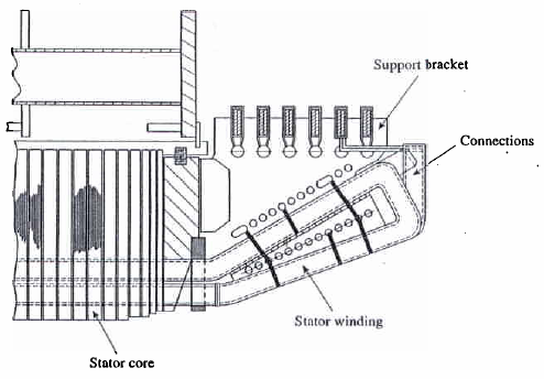
In addition to the blocking between the adjacent end windings, the later shall be attached to the surge rings with felt material inserted around the coil. The surge rings are made of insualted steel or fiberglass material. The same inspection procedure should be applied to the surge ring attachements, but a special attention is to be given to steel surge rings due to the risk of ground short circuit when the insulation is damaged. In many cases, the use of mirrors is made necessary because the signs of deterioration are located in restricted areas. In old windings, it is common to notice electric trackings or burn-like spots on the insulation of the surge rings or the coil. This is usually due to electrostatic discharges from the coils, and could be corrected by adding few layers of impregnated insulation.
In the same area, the surge ring support assembly must be inspected to make sure it remains in sound condition and able to transmit the coil forces to the frame of the machine.
RTD and TC
Resistance Temperatre Detectors (RTD) and Thermocouples (TC) are used to measure the temperature in the windings, along the path of cooling air or hydrogen, and around heat exchangers. The wiring has to be tightly secure along its path around the coils, frame and casing. Broken wires during operation are identified and repaired.
The winding RTDs are inaccessible because they are embedded inside the slot between two legs of 2 coils. Therefore, when a damaged RTD is identified it could not be replaced. It is left in place with its wire disconnected, and a new RTD is glued close to the damaged one, usually in the beginning of the end winding portion.
Typical Asphalt (Thermaplastic) and Thermosetting Winding Problems
Asphalt base coils are included in the group of Thermaplastic insulation systems. Asphalt insulation began to be used in the 1920s and 1930s to bind mica flakes asphalt (micafolium) or to bind mica flakes to a tape (asphalt mica tape). They were used until the 1960s, when they were replaced by Thermosetting insulation systems.
They are known to have problems related to asphalt bleeding and soft spots. This is due to the fact that asphalt tends to migrate along the coil to areas of lower pressure, and sometimes even to flow out of the coil. This can be seen as bulging in some areas of the coil. The normal thermal cycling often leads to cracking and tape separation just outside the slot portion of the coil. Insulation bulging is more often seen in the air duct, between laminations packets, thus, whenever possible, the use of a boroscope is recommended to ensure better evaluation of the severity of the damage.
Unlike thermoplastic insulation systems, the thermosetting insulation sysytems become dry and brittle when exposed to elevated temperatures. This will be followed by voids created in the insulation and increasing partial discharge activity.
In addition to visual inspection of the winding, many electrical tests could be performed on the winding to evaluate its condition, such as Hi-Pot, Polarization Index, insulation Power Factor, and Partial Discharge Analysis.
Circuit Bus and Pole-to-Pole Connections
The circuit ring buses are made of insulated copper that is square or round shaped. their number depends on the number of parallel paths per phase. The pole-to-pole connections are usually located behind the end windings and they connect the polephase groups of each phase together. Both the circuit rings and the pole-to-pole connections have to be inspected for insulation cleanliness, cracking, and partial discharge activity. The integrity of their ties and supports are also to be checked.
Corona Activity
Corona activity is defined as the ionization of a gas when exposed to an intense electric field. It is a high speed discharge with frequencies ranging between 40 kHz and 100 MHz. The generator corona activity can be divided into three different types.
– Corona activity in the end-windings: the common sign is a white powder where the end winding coils are at minimum distance.
– Internal partial discharges: they occur in the voids inside the insulation of the machine, or between different layers of the insulation with tape separation. This usually occurs in the overhang areas as the insulation is not as well compressed as in the slot section. They are difficult to find visually, but electric testing can help to detect them.
– Slot discharges: this occurs between the ground wall insulation and the iron core.
Discharges in the air produces ozone having a characteristic smell. They are also difficult to identify visually, but the condition of the semiconducting tape or paint covering the coil may indicate the probability of the existence of partial discharges.
Many electric tests can help detecting corona activity. Among them, the corona handheld probe test, black out test, or online partial discharge measurements. Other common testing, such as power factor tip-up or polarization index, could also provide an indication of partial discharge.
Slot Wedging
Wedges control the tightness of the coil inside the slot. The wedge condition is evaluated by tapping the wedge with a small hammer to classify the sound as a tight or hollow wedge. This is a subjective test and it takes an experienced professional to identify the wedge condition. A loose wedge is due to coil shrinkage or loose slot packing. During a wedge survey, all wedges are tapped and their condition is recorded on a special form, like the sheet presented in section 4. If when more than 25% of the wedges are loose, a complete rewedging is recommended.
A more rapid and objective survey of the wedges was recently introduced. It consists in a hand-held tapping electronic instrument. The machines using ripple spring in the slots tend to have better tightness over the long run. The condition of the ripple spring itself can be checked through pre-perforated wedges allowing the measurement of the ripple spring compression.
Another problem related to wedges is the end wedges slipping out, even when the end wedges have been glued. Recent designs almost eliminated this situation using special locking end wedges. The same problem applies to the slot fillers, in particular for the non VPI machines.
It is important to make sure that the coils are well seated in the bottom of the slot. This can be checked using a filler gauge or a mirror that allows observation of the end core area.
Other Stator Major Components
This section includes the survey of the other major components of the stator.
Cleanliness of the Stator Bore
An excessive discoloration and flaking of the paint on the casing, frame and the stator bore indicates possible overheating. This may be due to oveloading or improper air flow or any other related problem with the cooling system. While performing a visual inspection the following situation may be encountered:
– A large amounts of carbon dust is an indication of a deficient sealing between the collector enclosure and the other parts of the machine.
– Copper dust, sometimes mixed with oil, indicates a possible excessive pounding of the rotor-field conductors.
– Water accumulated in the bottom is usually related to leaking in the heat exchanger.
– Presence of iron powder in the bore or frame may indicate a loose stator core.
Stator Vent Condition
Clogged vents restrict the flow of the cooling gas and may result in machine derating or excessive heating. This is common in industrial generators operating in unfriendly environments, in particular with old open air machines.
This problem can be detected as hot spots with unusual differences in temperature readings depending on their locations. In some cases, air duct clogging could be caused by massive accumulation of red iron oxide powder due to a very loose core.
Iron Oxide Deposits and Stator Core Clamping
During inspection, a quick identification of the iron oxide deposits can be made using a small magnet. If the powder or the mixture of powder and oil responds to the magnetic attraction, this means that a significant proportion of iron oxide is present. Iron oxide can result from loose laminations or loose wedges. In the first case, the reddish powder will be spread out over a large area determined by the cooling air path. In the second case, the powder tends to cencentrate between the wedge and the iron.
Loose wedges may abrade themselves, then they come out of the slot groove. This also may lead to the loss of semiconducting paint, and will be detrimental to the coil insulation.
Stator Core Clamping
After years of operation, thermal cycling and vibration may lead to the abrasion of the interlaminar insulation, broken laminations, and possible hot spots.
Particular attention should also be given to the core compression bolts, through bolt insulation, and core compression fingers. Other detrimental effects could be related to the deterioration of the coil insulation due to core hot spots, increasing core losses, vibration, and audible sound levels.
Typically, during the inspection, a 10-mils blade can be used to check the looseness of the laminations. It is a common practice that if the blade enters more than 25 mm, the core must be retightened. Care must be taken not to damage the coil insulation, or break the blade and leave the broken piece between the laminations. When necessary, the core should be retorqued to the value recommended by the manufacturer (typically around 150 psi of core pressure).
High Voltage Bushings and Stand-off Insulators
The following notes apply to the different arrangements of terminal boxes and bushings. Lead bushings are subject to damage due to excessive vibration, overheating of the leads, or sudden load changes. They should be inspected for evidence of cracks, oil leaking and looseness.
The same attention should be given to the stand-off insulators sometimes used to support the lead and neutral busses. External surfaces should be cleaned to avoid tracking that leads to an eventual short circuit to ground.
Many lead failures are caused by the melting of the flexible connections, which arises from fatigue cracking when they are badly supported by the stand-off insulators. Also, cooling of the bushing has to be checked for any evidence of clogged passages in order to avoid overheating.
Heat Exchangers
Turbogenerators have their air-water or hydrogen-water heat exchangers inside the machine casing. They should be inspected for cleanliness and leaks, as the two major concerns are the clogged water tubes and water leaking. The water ducts could be clogged due to corrosion and deposit of minerals, leading to poor heat transfer properties and reduced water flow.
General mechanical intergrity is also to be inspected to avoid vibration and the loss of bolts, with potential harm to the rotating machine.
Space Heaters
The role of space heaters is to keep the moisture away from the machine when it is out of service. By warming the surrounding air, the water vapor does not condense on the windings.
Inspection should include checking for loose connections and general integrity of the space heaters and their wiring. The resistance continuity is also to be tested.
Bearing Insulation
Voltages and currents are induced in the shaft during normal operation of the machine. They have to be kept at very low values to avoid bearing failures. The most common origin of these induced currents is the excitation spikes, in particular with static excitation systems having high harmonic content. They also can be caused by magnetic asymmetries affecting the reluctance path and inducing voltages in the shaft.
Voltages as high as 150 V are not uncommon and the resulting current pitting may damage the surface of the bearing babbit. This damage is more mechanical than thermal and is caused by small electric discharges. These are recognized during inspection using a magnifying glass, as they appear as shiny rounded spots.
Minimizing shaft voltages is usually achievable by introducing shaft grounding devices and by increasing the bearing insulation. The bearing oil shall be maintained clean and free of contaminents, such as carbon dust, to keep the insulation resistance high.
The bearing insulation resistance can vary in a large range from 100 kOhms to hundreds of MegaOhms. To be on the safe side, it should be maintained in the MegaOhms.
Core Laminations
It is not uncommon to find broken or bent laminations during the removal or replacement of the rotor, leading to a short circuit between these laminations. For some cases, the core laminations are bulging into the air ducts or vent areas due to weakened lamination, which arise from vibration, or weak supports. The position of the duct spacer, usually an I-shaped separator, has to be checked, as it may move toward the center of the machine.
Continue: ………………………………………………………………………
Large Electrical Generators Condition Assessment – Rotor Inspection