This article is about piping material selection guide pdf, Material selection for piping systems pdf, pipe material selection for water supply, piping material technical specification, piping materials for oil and gas and pipe material grades.
This article addresses the fundamental aspects of selecting materials for constructing different piping systems. It is essential to choose the appropriate materials based on the type of fluid that will be transported through these pipes. These material selection guidelines complement the standards established by piping codes, specifically ASME B31. Additionally, they take into account various specifications that govern chemical, mechanical, and dimensional properties.
Key Points:
- Material Selection is Critical: The choice of materials for piping systems is a critical decision, as it directly impacts the safety, reliability, and performance of the system.
- Compliance with Piping Codes: Piping materials must adhere to the guidelines set forth by industry-standard piping codes like ASME B31. These codes provide essential requirements for designing, constructing, and inspecting piping systems.
- Additional Requirements: Beyond the piping codes, materials must also meet specific requirements and limitations concerning their chemical composition, mechanical properties, and dimensions. These additional criteria are typically outlined in relevant industry specifications.
- Refer to Other Standards: While this article provides general guidance on material selection, it’s important to note that other Saudi Aramco Engineering Standards (SAES) cover more specialized aspects of piping systems, such as gasket materials (SAES-L-109) and valves (SAES-L-108). These standards should be consulted for detailed information on these specific components.
- SAES-L-132: The article mentions SAES-L-132, which likely provides further details on material selection criteria and requirements specific to Saudi Aramco’s operations. Engineers and professionals involved in piping system design and construction should refer to this standard for in-depth guidance.
Selecting the right materials for piping systems is a critical aspect of ensuring their safety and functionality. These material choices should align with established industry codes and standards, as well as meet specific criteria outlined in relevant specifications like SAES-L-132. Additionally, when dealing with gasket materials and valves, it’s essential to refer to the respective SAES standards for comprehensive guidelines.
Pipe Material Selection
This section outlines the guidelines for material selection in piping systems based on the service environment and conditions. It also emphasizes the importance of using materials that are resistant to specific types of cracking in wet, sour services.
Key Points:
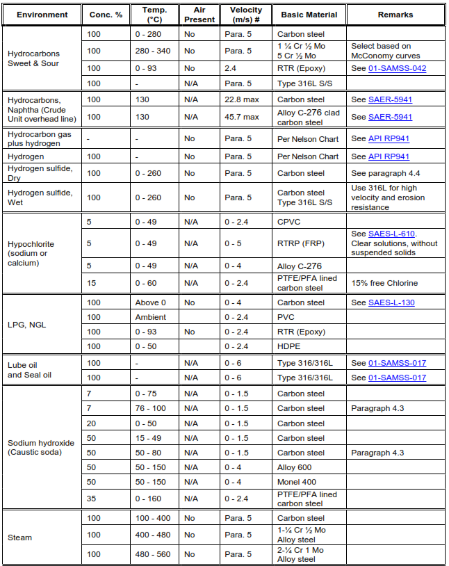
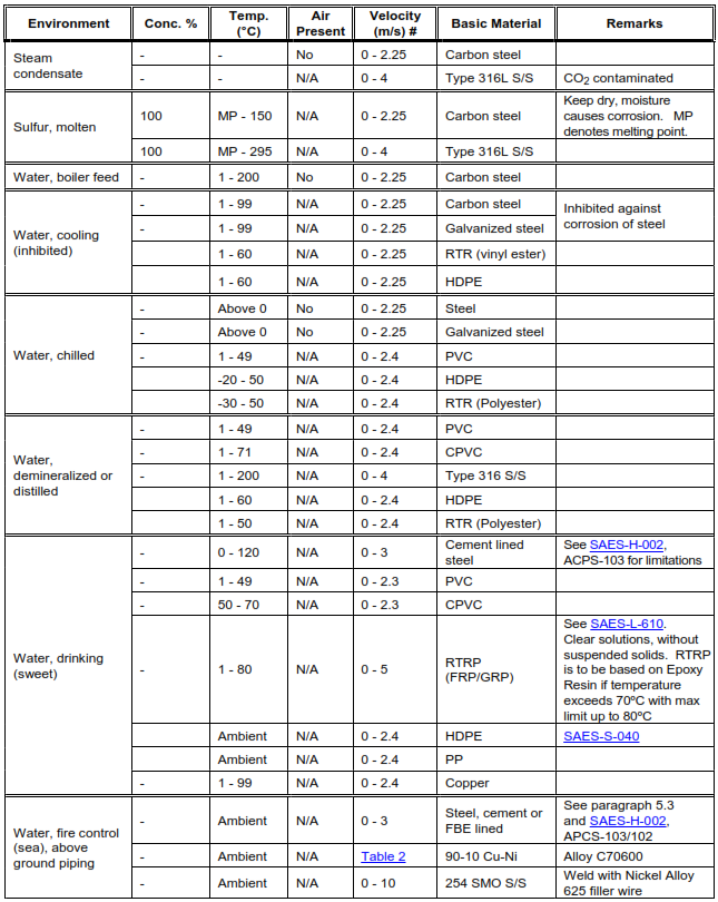
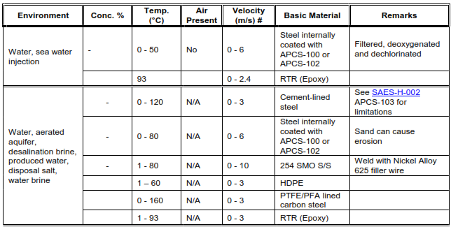
- Material Selection for Service Environment: Piping materials, including pipes and piping components, must be chosen based on their compatibility with the service environment. The materials listed in Table 1 of the standard are recommended for specific fluids and design conditions. However, equivalent or superior materials may be used with approval from the assigned Engineering Specialist in the Consulting Services Department. If the service conditions differ from those listed in Table 1, consultation with the Engineering Specialist is advised.
- Reference to SAES-L-105: For additional information on pipe classes, the standard refers to SAES-L-105. Pipe classes are essential for specifying the materials and construction details for various piping components.
- Stress Relief Heat Treatment: Carbon steel piping, including bends and welds, must undergo stress relief heat treatment in the temperature range of 595 to 650°C for certain services, as indicated in the remarks column of Table 1. Stress relief heat treatment helps reduce residual stresses in the material, enhancing its mechanical properties and reducing the risk of failure.
- Sulfide Stress Cracking (SSC): Materials used in wet, sour services, as described in SAES-L-133, must be resistant to sulfide stress cracking (SSC) following the guidelines of NACE MR0175/ISO 15156. The materials that meet these requirements include specific types of pipe, fittings, and flanges, as outlined in the standard.
- Hydrogen Induced Cracking (HIC): In wet, sour services where hydrogen induced cracking (HIC) is a concern, specific materials are required. These materials are detailed in the standard and include seamless pipe, submerged-arc welded pipe, HFW (ERW and HFI) pipe, fittings, and flanges, meeting the requirements of API SPEC 5L and other specifications.
- Materials Not Meeting HIC Requirements: Piping, fittings, or flanges that do not meet the requirements for resistance to hydrogen induced cracking should not be used in wet, sour services where HIC is a possibility. This emphasizes the critical role of material selection in ensuring the integrity of the piping system in corrosive environments.
This section provides clear guidance on material selection for piping systems, taking into account the service environment and specific cracking risks. It emphasizes the importance of selecting materials that are compatible with the service conditions to ensure the safety and reliability of the piping system. Compliance with industry standards and specifications is essential in material selection.
Maximum and Minimum Velocities
This section of the standard outlines the permissible velocity limits for various fluid types and conditions within carbon steel piping systems. It specifies the maximum and minimum velocities allowed for different situations to ensure safe and efficient operation.
Key Points:
- Exceptions for Proprietary Piping: The maximum and minimum velocity limits specified in this section do not apply to proprietary piping systems (e.g., metering skids, surge relief skids) or piping systems requiring flow balance in branch segments (e.g., firewater spray/sprinkler systems). These cases may have unique velocity requirements.
- Single-Phase Gas Lines: For in-plant gas piping (excluding relief and flare flow), the maximum velocity is limited to 18.3 m/s to prevent excessive noise. Higher velocities may be acceptable for simpler piping layouts with fewer fittings and valves, subject to approval by the Engineering Specialist. The minimum velocity in gas lines should be 4.6 m/s to prevent water accumulation.
- Liquid Lines: Single-phase liquid lines (not specified in Table 1) have a maximum velocity limit of 4.6 m/s. Higher velocities may be considered for special cases or intermittent services with Engineering Specialist approval. The minimum velocity in liquid lines is 1 m/s to prevent solids deposition and water accumulation.
- Gas/Liquid Two-Phase Lines: Except for liquid relief and blowdown lines, flow velocities in flowlines and other lines transporting gas and liquid in two-phase flow shall not exceed the fluid erosional velocity (reference API RP14E, paragraph 2.5.a) as determined by equation (1):


- Steam Lines: The velocity range for continuous service in insulated steam lines is 30-40 m/s for saturated steam and 40-60 m/s for superheated steam. For vent steam, the maximum velocity limit is 60 m/s.
- 90-10 CuNi Piping: The maximum allowable fluid velocity in 90-10 CuNi piping depends on the pipe size, as specified in Table 2 of the standard.
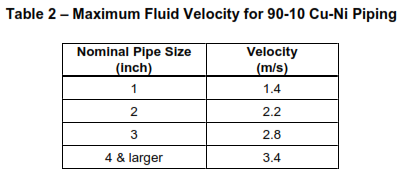
- Firewater Systems: When sizing firewater systems, the maximum velocity of water at the outlets (hydrants and monitors) should not exceed two times the maximum velocity listed in Table 1 for the pipe material.
- Relaxation of Velocity Requirements: In certain cases, velocity requirements may be relaxed to allow the installation of pipeline sizes that can be inspected with single-diameter In-Line Inspection (ILI) tools. Approval from the Chairman of the Materials and Corrosion Control Standards Committee is required for such relaxation.
- DGA Velocities: Maximum velocity limits for carbon steel piping in rich DGA (Dissolved Gas Analysis) are 1.5 m/s, while it is 3.05 m/s for lean DGA.
These velocity limits are crucial for maintaining the integrity and performance of the piping systems while ensuring safety and preventing issues like noise, erosion, and accumulation of materials within the pipelines. Compliance with these limits is essential in the design and operation of piping systems.



International Codes and Standards used for this article.
American Petroleum Institute
API RP14E – Design and Installation of Offshore Production Platform Piping Systems.
API RP571 – Damage Mechanisms Affecting Fixed Equipment in the Refining Industry.
API RP941 – Steels for Hydrogen Service at Elevated Temperatures and Pressures in Petroleum
Refineries and Petrochemical Plants.
API RP945 – Avoiding Environmental Cracking in Amine Units.
API SPEC 5L – Specification for Line Pipe.
American Society of Mechanical Engineers
ASME B31.1 – Power Piping.
ASME B31.3 – Process Piping
ASME B31.4 – Liquid Transportation Systems for Hydrocarbons, Liquid Petroleum Gas, Anhydrous Ammonia, and Alcohols.
ASME B31.8 – Gas Transmission and Distribution Piping Systems
American Society for Testing and Materials
ASTM A106 – Standard Specification for Seamless Carbon Steel Pipe for High-Temperature Service.
ASTM A333 – Standard Specification for Seamless and Welded Steel Pipe for Low-Temperature Service.
International Organization for Standardization
NACE MR0175/ISO 15156 Petroleum and Natural Gas Industries Materials for Use in H2S-Containing Environments in Oil and Gas Production.
National Association of Corrosion Engineers
NACE Corrosion Data Survey, Metals, 5th edition, 1979
NACE Corrosion Data Survey, Non-Metals, 5th edition, 1978
P-CR-001 Common Requirements, Process Design.