This article is about On Stream Inspection of Piping Procedure & method statement as well as off stream inspection.
1. SCOPE of WORK
2. PURPOSE
3. REFERENCE
4. RESPONSIBILITY
5. SAFETY CONTROL
6. METHODOLOGY FOR BASELINE SURVEY
7. ATTACHMENT.
On Stream Inspection of Piping Procedure | Method of Statement
1. Scope of Work
This method of statement or procedure will be applied for the baseline thickness survey (BLS) conducted during the EPC phase by CONTRACTOR for a purpose of On-Stream Inspection (OSI) by COMPANY for the Plants and Refinery Project.
2. Purpose
OSI monitoring is conducted after start-up of the plant for the systematic monitoring of piping, vessels and tanks for general loss of wall thickness and localized metal loss. Thickness Monitoring Locations (TMLs) are determined and OSI drawings are prepared as per SAEP-1135 and S-000-1261-001 “OSI Drawing Preparation Procedure”. The Baseline Survey (BLS) is conducted to obtain original wall thickness measurement of new piping and equipment and enable calculation of corrosion rates after years of the plant operation.
3. Reference
The following codes/standards and specification documents shall be applied as a part of the requirements of this specification.
SAEP-1135 (26 Apr 2009) On-Stream Inspection Administration.
SAEP-1142 (19 May 2009) Qualification of Non-Saudi Aramco NOT Personnel.
SAEP-1146 (20 Sep 2008) Manual Ultrasonic Thickness Testing.
SAES-L-133 (23 Jan 2012) Corrosion Protection Requirements for Pipelines, Piping and Process Equipment.
SAES-N-001 (6 Sep 2008) Basic Criteria, Industrial Insulation.
ASME Sec.V Article 5 Ultrasonic Examination Methods for Materials and Fabrication.
ASME Sec.V Article 23 Ultrasonic Standards.
API 510 (Jun 2006) Pressure Vessel Inspection Code: In-Service Inspection, Rating, Repair, and Alteration.
API 570 (Nov 2009) Piping Inspection Code: In-service Inspection, Rating, Repair, and Alteration of Piping Systems.
On-Stream Inspection Drawing Preparation Procedure.
Baseline Survey Procedure for On-Stream Inspection.
Corrosion Management Program for Plant.
4. Responsibility
O&M Engineer: Take responsibility of BLS activities.
QC Engineer: To educate inspectors and technicians, and monitor the activities.
Insulation Team: To provide insulation plugs to the TMLs where it is insulated.
QC Inspector: Manage the technicians and verify the measurement results.
Technician: Take baseline thickness measurements by UT instruments and record the measurement results in the thickness reports.
5. Safety Control
1) PPE: All personnel who will involve to this work at site shall wear the following PPE.
• Safety helmets
• Safety shoes
• Safety Spectacles
• Hand Glove
• Full body harness ( during work at height)
2) Confined Space Entry:
a) Before starting the work at confined space, work permit shall be submitted and approved.
b) No one may enter on without specific approval and a current work permit prior to enter to the skirt for equipment. The safety equipment, gas test and instruments are required.
c) All personnel involved in confined space entry work must have undergone confined space entry trainings.
d) Confined space entry trained stand-by person shall be present outside the confined space.
3) Grating removal:
a) Before grating removal for platform, work permit shall be approved and the gratings shall be removed by authorized personnel.
b) The personnel working for grating removal shall 100% tied off.
c) Barriers shall be provided around all grating openings (hard barriers)
4) Work at height:
During work at height, all personnel shall wear full body harness and 100% tie-off. All personnel shall have undergone work at height training.
6. Methodology for Baseline Survey
1) Manpower
BLS shall be conducted by UT technicians who were qualified and certified in accordance with employer’s written practice and pass Saudi Aramco qualification verification exam in accordance with SAEP-1142.
2) Timing
For Non-insulated equipment and pipes: BLS is conducted after installation of equipment and pipes. Basically those shall be measured on the painted surface. For insulated equipment and pipes: BLS is conducted after covered by insulation. Insulation team shall make window for plug at the measurement points before reading thickness.
3) Location
As basic requirement, in accordance with approved drawings and S-000-1261-001(On Stream Inspection Drawing Preparation Procedure), CONTRACTOR shall decide the thickness measurement locations at site. However, considering accessibility during plant operation, CONTRACTOR may choose the location which is easy to access from the platforms especially for shell of columns. If location changed due to accessibility or some other reasons, the revised location to be reflected to As-Built drawings and 3D model.
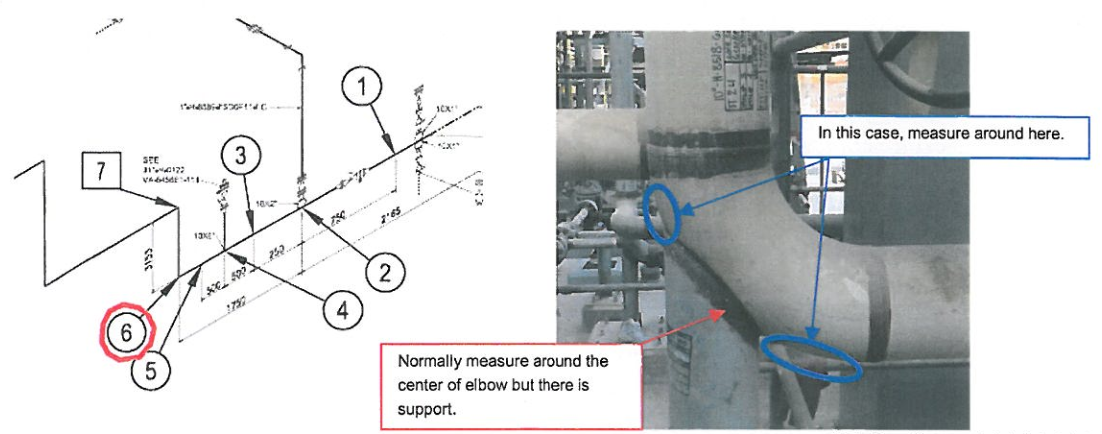
For injection(INJ) point (e.g. J11-H-110(INJ)), there is dimension for the each measurement locations in the drawing. Therefore, UT technician should measure the thickness at the exact location as per the drawing. However, if there is a difficulty, for example inspection location covered by piping support, UT technician can measure thickness beside of the support.(Normally downstream side.)
4) Preparations
1. CONTRACTOR shall confirm and prepare access to the measurement location such as scaffoldings. Also, CONTRACTOR shall submit required PTW (Permit to work) before
starting of the work and then, all personnel who involved in this work at site shall follow it.
2. The test area shall be free of corrosion, insulation, weld spatter, surface irregularities, or foreign matter that might interfere with the examination. Remove as little material as possible when cleaning.
3. Where coatings interfere with the examination, the coating shall be removed and recorded.
5) Insulation Plug
The size of plugs for each insulated locations shall follow S-000-1261-002 Para 7.3. Those will be provided by insulation team.
6) UT instruments
The technician prepares a UT instrument,
• which; is a model approved by COMPANY,
• shall have an A-scan display to assist the operator in discrimination of test resits,
• has a valid Calibration Certificate and daily calibration log.
The proper functioning of the examination system shall be checked and the equipment shall be calibrated by the use of the calibration standard at the beginning and end of each shift; every four(4) hours during the examination; when examination personnel are changed; when any equipment is changed; and at any time that malfuntioning is suspected. All calibration values shall be within ±0.05mm(0.002 inch) of the known thickness value. Also, the technician shall prepare couplant which should have good wetting characteristic for temperatures which may be incurred during the taking of measurements.
7) UT thickness measurement procedure
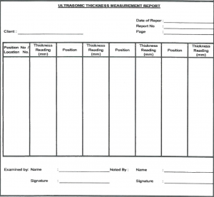
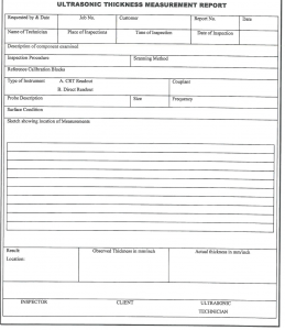
UT technician shall carry out thickness measurement as per the UT thickness measurement procedure that was already approved by COMPANY and record the reading on a format approved by COMPANY.(Refer to Attachment-1) Sticker with required detail shall be posted on the each inspected locations.
NOTE: All thickness readings shall be taken to two decimal places in millimeter.
8) Post Cleaning
All watar based couplant shall be completely removed from the specimen with a dry absorbent cloth.
9) Sticker
Sticker specifications are attached with this method of statement and are approved by COMPANY. (Refer to attachment-2) Those stickers shall be put on the inspected locations as below:
► Type A: TML on 4 inch and larger bore piping and equipment
► Type B : Insulated piping and equipment
► Type D : 3 inch and below bore of piping and nozzle on equipment. Since the space provided on this sticker type is small therefore two(2) stickers will be used on one(1) location; One sticker will be utilized to Note the Circuit Details and other will be utilized to Note the measurement location number.
NOTE: It is required to remove sands, oils and any other foreign materials on the surface before put sticker on the each measurement locations so that it will stick properly.
9) Marking
Marking pen which is applicable for max operation temperature shall be used. Therefore, UT technicians shall use marker pens which have been provided by CONTRACTOR for this specific work. Unauthorized marker pen shall not be used for this work. Also, the following information shall be described on stickers.
For EQUIPMENT
1. Equipment Number (e.g. J10-E-XXXX)
2. Measurement location number (e.g. 1, 2, 3..)
For PIPE
1. Corrosion Circuit Number (e.g. J10-P-XXXX)
2. Measurement location number (e.g. 1, 2, 3..)
10) Record
Each sub-contractor shall submit UT thickness report to CONTRACTOR as per approved
procedures. Based on those records, CONTRACTOR shall summarize the BLS data by using
record forms which have been approved by COMPANY as appendix of drawings.(Refer to attachment 3 and 4 as sample). And Contractor shall submit two different UT Reports. One is covering Pipe and other is Covering Equipment as per report.
7. Attachment
Attachment-1 : UT measurement procedure
Attachment-2 : Sticker specification
Attachment-3 : Sample of record form for equipment
Attachment-4: Sample of record form for piping


