1.0 SCOPE
2.0 PURPOSE
3.0 REFERENCES
4.0 NDT PERSONNEL
5.0 EQUIPMENT
6.0 SURFACE PREPARATION
7.0 EQUIPMENT CALIBRATION
8.0 MEASUREMENT
9.0 POST CLEANING
10.0 REPORTS
REPORT FORMAT
Ultrasonic Examination Procedure for Thickness Measurement
1. SCOPE
This procedure shall be applicable to all structural materials pipe line materials,
piping spools and joints, tanks, vessels and plates made of carbon steel and alloyed steel.
2. PURPOSE
This procedure describes the techniques adopted for measurement of material
thickness by Ultrasonic Method using flaw detectors equipped with A-Scan display.
3. REFERENCES
3.1 ASME Section V, 2010 Edn Article 5
3.2 ASME Section V, 2010 Edn Article 23, SE 797
3.3 NDT/CERT/01 (Latest Rev.): Procedure for Qualification & Certification ofNDT
Personnel.
3.4 Operating and Instruction Manuals from Krautkramer and Panametric for
respective UT Machines.
3 .5 Contract Specification.
4. NDT PERSONNEL
4.1 Personnel performing this procedure shall have been certified as per the
procedure NDT/CERT/01 (Latest Rev) and ANS/ASNT CP-189.
4.2 Personnel qualified to UT Level II or UTT Level II can perform this examination.
5. EQUIPMENT.
5.1 Ultrasonic Flaw Detector: (A-Scan), Ultrasonic D-meter with A-Scan.
5.1.1 UT flaw detectors such as KRAUTKRAMER USM 50, USM SOL USN 20, USN 25,
PANAMETRICS EPOCH IIIB, SONATEST SITESCAN 140 or equivalent. UT D
meters such as Krautkramer DMS2, DMS, Panametrics MG2 Series or 37 DL
series.
5.1.2 Transducer Selection:
5.1.2.1 Krautkramer MSEB2, Panametrics D 797 series probes or equivalent
shall be selected for coarse grained materials ranging in thickness
from 2 mm to 400 mm at temperature ranges from 20″C to 60€.
5.1.2.2 Krautkramer MSEB4, DA 201, DA 301, DA401 and Panametrics D
790 series probes or equivalent shall be selected for fine grained
materials ranging in thickness from I mm to 500 mm at temperatures
ranges from 20 to 60€.
5.1.2.3 SEB4KF8 probes shall be selected in critical positions where access is
limited for other probes.
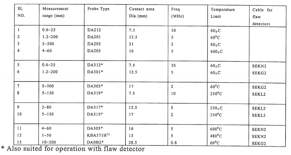
5 .1.2.4 Panameterics D790 series probes can be selected for high temperature
up to 500 deg C. Panametrics D 797 series probes can be selected for
temperature up to 400 deg. C. For Krautkramer brands, temperature
above 60″C table 1 has to be referred for selection of proper probes.
Table I. Probe selection for high temperature service.
5.2 COUPLANTS:
5.2.1 Motor Oil, grease, cellulose gel shall be used as a couplant as
indicated in the operating manuals of UT Machines.
5.2.2 couplants shall be selected with due consideration towards the
temperature of the examination surface.
5.3 CALIBRATION BLOCKS:
5.3.1 Calibration blocks shall be of known thickness and of the same
material specification as the material under examination. Example of
the calibration block is shown in Figure 1 below.
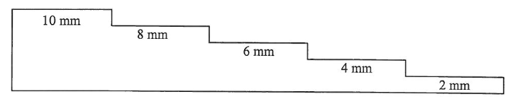
5.3.2 The temperature of the calibration block and the surface to be examined shall be within 14 degree Celsius of each other.
5.3.3 Step wedges shall have a thickness step near the minimum range to be examined, a step near the maximum range to be examined and a step in between the minimum and maximum.
6. SURFACE PREPARATION:
- The base metal on each side of the weld shall be free of weld spatter, surface
- irregularities, of foreign matter that night interfere with the examination
- Ensure that the surfaces to be examined are clean and free of any materials which
- will interfere with the transmission of the sound into the material under
- examination.
- The condition of the examination surface shall be determined by the examiner to
- be acceptable for UT examination.
- The temperature of the examination surface shall be determined to ensure that the
- correct transducer and couplant has been selected.
7. EQUIPMENT CALIBRATION:
7.1 GENERAL
- Screen height linearity shall be performed at the beginning of each period of extended use or every three months, whichever is less.
- The screen height linearity evaluation shall be performed in accordance with procedure WI 111-1
- Amplitude control linearity evaluation for A-scan instruments.
- Amplitude control linearity shall be performed at the beginning of each period of extended use or every 3 months, whichever is less.
- The amplitude control linearity evaluation shall be performed in accordance with procedure WI 111-1.
7.2 Calibration
- The proper functioning of the examination system shall be checked and the equipment shall be calibrated by the use of the calibration standard at the beginning and end of each shift; every four ( 4) hours during the examination; when examination personnel are changed; when any equipment is changed; and at any time that malfunctioning is suspected.
- 7 .2.2 Calibration blocks shall be at ambient temperature during calibration. Calibration blocks shall not be cooled or heated for cryogenic or high temperature applications. A low viscosity couplant such as Ultragel II shall be used for calibration. High viscosity couplants are not acceptable for calibration but are usually required for high temperature measurements.
- 7.2.3 The equipment shall be calibrated using a two-point calibration range that overlaps the expected measurement range, i.e., select a calibration block or step wedge thickness value greater than the maximum expected measurement value and a calibration block or step wedge value less than the expected measurement value.
- Apply coup I ant to the step wedge or calibration blocks and apply firm steady pressure to the transducer during calibration.
- All calibration values shall be within± 0.002 inch of the known thickness value.
- If at the end of the shift the instrument has drifted more than 0.002 inches consideration should be given to retaking all of the measurements since the last calibration.
- Button-type calibration blocks, on the front of ultrasonic thickness gauges, shall not be used for calibration.
7.3 STRAIGHT BEAM CALIBRATION FOR A-SCAN FLAW DETECTORS
- A-Scan instrument without digital display
- Select a calibrated step block (1-10, 2-20 or suitable thickness, with the anticipated thickness range ).
- Take the highest thickness in the step block and couple the probe on it.
- With range and delay control knobs the left edge of the echo can be set at CRT position 10.
- Take any other lower step of known thickness to the block and couple the probe on it. With range and delay control knobs set the left edge of the echo at … appropriate on horizontal position trace on CRT.
- Now the horizontal range of the machine has been set to the desired range. Adjust the gate such that the left edge of the 1st switch wall echo from the material whose thickness is to be measured is just outside the right edge of the gate.
- During scanning sound alarm is switched on such that comes and the gate alarm will go on. That will indicate in that particular area thickness is less than the nominal wall thickness. Extent of reduction on thickness can be calculated from the machine.
- A-Scan instrument with digital display
- Determine the anticipated thickness to be examined and select a calibration block which includes that thickness range.
- Select proper unit of length on the machine setup (either in inch or mm) depending on calibration block as well as the unit in which final measurement is to be done.
- Set the proper sound velocity in the instrument i.e 5920 meter/sec. for plain carbon steel.
- Place the transducer on the thinner section of the calibration block and adjust the delay until the left edge of the indication aligns with the correct CRT increment.
- Place the transducer on the thicker section of the calibration block and adjust the range control until the left edge of the indication aligns with the correct CRT.
- Replace the above steps until both indications appear on their respective increments.
7.3.14 Adjust the gate to display the thickness of the selected step. If the
thickness displayed is not correct repeat the above steps.
7.4 CALIBRATION FOR D-METERS WITH A-SCAN DISPLAY:
D-meters calibration shall be performed as per the manufacturer recommendation
specified in the respective operation Manuel.
8. MEASUREMENT:
8 .1 For proper sound coupling the transducer must be pressed firmly against the test surface in the same way it was followed during calibration. On small diameter cylindrical surfaces such as pipes, hold the transducer so that the sound barrier material visible on the probe face is aligned perpendicular to the central axis of the pipe.
8.2 While firm hand pressure on the transducer is necessary for good readings, the probe should never be scraped along or twisted against a rough metal surface. This will scratch the face of the transducer and eventually degrade performance. The safest technique for moving a transducer along a rough surface is to pick it up and reposition it for each measurement, not to slide it along.
8.3 Examinations shall be conducted from the OD surface or ID surface, as
applicable.
8.4 If the surface temperature is below 32F (0 °C) or above 215°F (101 °C), the
surface temperature shall be measured and recorded.
8.5 Apply couplant to the probe or the specimen surface. For high temperature
measurements, couplant always applied on probe space.
8 .6 The transducer acoustic barrier shall be placed perpendicular to the center axis when taking measurements on pipe or round objects up to 24 inches in diameter. The acoustic barrier orientation is not important on pipe and round objects greater than 24
inches in diameter.
8. 7 The transducer shall be held flat on the surface then slowly rocked tangentially after contact to find the lowest reading. All digital readings shall be verified by viewing the A-scan presentation on the instrument as doubling effects can give false
readings on digital outputs. The lowest reading shall be recorded. For difficult
readings, additional gain may be required to avoid grinding the transducer into the
surface.
8.8 A valid reading is one that can be maintained on the gauge display for several
seconds and the value is steady within± 0.002 inch
8. 9 Thickness readings shall be measured and recorded to three decimal places.
8.10. Correction for the change in ultrasonic sound velocity in metal is not
required within a thickness range of O to 1 inch. Temperature correction shall be
performed for metal thickness greater than 1 inch for temperatures below 32°F and
over 2 l 5°F. The following formula shall be used:
Ta= Tm x [1.007 – (0.0001 x Temp)]
Where:
Ta= the actual thickness of the part
Tm = measured thickness of the part
Temp = surface temperature in F
8 .11 The transducer face shall be cleaned before each measurement at
temperatures greater than 400F as evaporated couplant can leave deposits on the
transducer face.
8.12 Use the “touch test” to monitor the transducer temperature. If the transducer
face is too hot to be held against your skin then it shall be cooled in air or water prior
to taking readings.
9.0 POSTCLEANING:
All couplant applied on the surface shall be completely removed from the specimen by
wiping with a dry absorbent cloth or paper towel, fresh water wash etc.
10.0 REPORTS:
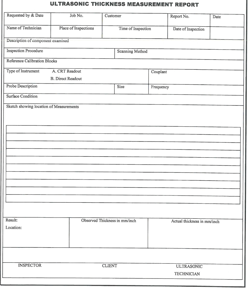
10.1 All measurements are recorded in Ultrasonic Thickness Measurement report, a
format of which is shown in Exhibit I.
10.2 After filling up the complete report it should be countersigned by client’s
inspector and filed for future reference.
10.3 On the basis of customer requirement, customer report format can be used for
spot thickness measurement reporting.
Ultrasonic Examination Procedure for Thickness Measurement