- SCOPE OF WORKS
- PURPOSE
- RESPONSIBILITIES
- REFERENCES
- PROCEDURES
- General Requirements
- Material Receiving
- Installation
- Pre-Commisioning
- TOOLS AND EQUIPMENTS
- INSPECTION AND TEST
- QUALITY CONTROL.
- SAFETY
- DOCUMENTATION
- JOB HAZARD ANALYSIS
1.0 SCOPE OF WORK
1.1 This procedure covers the technical requirements for the execution of HVAC Electrical installation works for Jazan Refinery and Terminals Project.
2.0 PURPOSE
2.1 The purpose of this method statement is to outline the procedure of the installation of electrical systems for Heating, Ventilation and Air Conditioning for Saudi Jazan Refinery & Terminal Project Package 12 including the requirements for safety of personnel and Quality Assurance/Quality Control.
3.0 RESPONSIBILITIES
3.1 Construction Manager
3.1.1 Assign particular responsibilities and authorities to construction personnel.
3.1.2 Executes the construction according to the construction plan and the work procedure.
3.1.3 Coordinate with the owner representative, Construction Engineer, HSE Manager and E & I QC Inspector for the safe and proper execution of the work.
3.1.4 Give specific attention to all safety measure and quality control in coordination with HSE Manager, QC Manager and in line with Approved HSE Plan and Approved Quality Plan.
3.1.5 Reviews the construction plan and work procedures referring to this work instruction, which shall include the following items:
(i) Owner’s requirements in the Specification
(ii) Work procedures, Inspection and Test Standards, ITP and checklists.
(iii) Input plan for materials, equipment and workers.
3.2 E & I QC Engineer
3.2.1 Ensure that all works are carried out as per work procedures/MS and other quality procedure.
3 .2.2 Maintain inspection and records complete for future references.
3 .2.3 Reviews the construction plan and the work procedure related with this work.
3.2.4 Checks whether the construction plan and the procedure are well observed in the actual construction.
3 .2.5 Controls the Inspections and Tests related with this work.
3.2.6 He shall coordinate all inspection with Company including submitting advance notification for inspection.
3.2.7 He shall be responsible for the final AS-BUILT and QC dossiers for submission to company.
3.3 Safety Officer
3 .3.1 Check the possible hazards of the activities to be done and co-ordinate to the site supervisors to rectify if there is any to ensure the safety of the workers at job site.
3.4 Supervisors
3.4.1 Responsible for confirming the installation locations from the approved drawings.
3.4.2 Organize tools and equipments required at work site and sequence of activities to be carried out for the work as per document.
3.4.3 Ensure required work permit and copy of job safety analysis at site.
3.4.4 Conduct daily tool box meeting prior to start of work.
3.5 Subcontractor
3.5.1 The subcontractor shall be responsible for the direct implementation of this method statement.
3.5.2 Subcontractor shall prepare documents for notification of inspection and of the construction record (Inspection and Test Report) in accordance with related procedure.
3.5.3 Subcontractor shall utilize and maintain the revised documents and drawings up-to-date for the construction work.
3.5.4 Subcontractor shall use Company approved documents and numbering system in accordance with project’s specification.
3.5.5 Inspection Test Report(s) shall be submitted to Contractor or Owner/Engineer Representative.
3.5 .6 Inspection Test Report(s) shall be approved and reviewed for its completion by relevant Contractor/Company.
4.0 REFERENCES (APPLICABLE CODES & STANDARDS )
Particular reference shall be made to the latest edition of the following international and national industry codes, standards and specifications which apply for the construction work involved in this method statement which include but are not be limited to the following:
I. SAES-P-104 – Wiring Methods and Materials.
II. SAES-P-111 – Grounding.
Ill. SAES-P-119 – Onshore Substation.
Iv. SAES-J-902 – Electrical Systems for Instrumentation.
V. NFPA 70 – National Electrical Code.
VI. NEMA VEI – Metal Cable Trays Systems.
VII. NEMAVE2 – Cable Tray Installation Guidelines.
VIII. IEEE – Institute of Electrical and Electronics Engineers.
IX. NEMA – National Electrical Manufacturer’s Association.
X. ANSI – American National Standards Institute.
XI. NETA – Inter National Electrical Testing Association.
XII. SATIP-P-104-03 – Cable Tray Fittings and accessories.
XIII. SATIP-P-104-05 – Conduit, Fittings and accessories.
XIV. SATIP-P-104-08 – HVAC Equipment.
5.0 HVAC SYSTEM ELECTRICAL WORK PROCEDURE
5.1 General Requirements
5.1.1 Cable trays/ladders and accessories conforming to applicable standards e.g. NEMA VE-I, IEC-61537, NEC, SAES-P-104.
5.1.2 Conduits used indoor but not embedded on concrete for HVAC controls may be Electric Metallic Tubing (EMT).
5.1.3 Conduits to be installed for indoor power application and for outdoor will be rigid steel, hot-dip galvanized (HOG).
5.1.4 Conduits to be installed in severe corrosive area e.g. battery room will be PVC coated rigid steel conduit.
5.1.5 Cables to be installed will be as per approved material submittal, approved drawing and applicable standards.
5.1.6 Equipment, enclosures, boxes, field devices and other installation materials will be as per approved submittals and suitable for the area classification.
5.1.7 Adequate ventilation will be provided by the construction team to prevent inhalation of fumes, dusts and other particles by the workers as a result of cutting, grinding and other activities.
5.1.8 Sufficient lighting will be provided to prevent any incidents due to poor sight in the construction area.
5.1.9 Proper housekeeping will be implemented before and after each working day to minimize hazards.
5.2 Material Receiving
5.2.1 All materials delivered to site will be inspected jointly by ZP, DEC and SAPID engineers/inspectors in accordance with the approved Inspection & Test Plan.
5.2.2 Inspection results will be recorded in appropriate approved inspection checklist duly signed by respective QC inspector/engineers.
5.2.3 Proper storage and preservation of materials will be provided to ensure that materials will be in good condition and to provide protection against deterioration due to effects of environment conditions i.e. direct sun light, moisture, temperature, humidity, etc.
5.2.4 Cables will be tested for continuity and insulation resistance on reel. Results will be recorded in the checklist.
5.3 INSTALLATION
5.3.1 DDC Panel And Field Devices Installation.
5.3.1.1 DDC panel will be hauled from storage area to the location of installation by boom truck or other approved means that is sufficient to carry the
weight of the panel.Check and verify if the location/mounting floor foundation of Control Panel are in accordance with the approved design
and lay-out drawings.
5.3.1.2 DOC panel will be transferred in an upright position securely fastened on the truck while moving.
5.3.1.3 Upon unloading from the truck, the panel will be moved to its designated location by means of pallet jack with the anchor bolts already in place.
5.3.1.4 DOC panel will then be secured properly by tightening the anchor bolts to hold it to position while checking the level and alignment.
5.3.1.5 After installation, check the DOC panel for any items that might become loose during transportation.
5.3.1.6 Foreign objects will be removed inside the panel. Cover with plastic to prevent ingress of dirt and other particles from construction.
5.3.1.7 Fragile components accessible from outside like the Human-Machine Interface (HM!) and indication lights will be protected from physical damage by suitable means.
5.3.1.8 Installation of field devices will be done by qualified technicians in locations shown in the approved drawings.
5.3.1.9 As much as possible, devices will be installed only after installation of ducts, pipes and other mechanical services in order to prevent damage to instruments and in line equipment.
5.3.1.10 Devices will be installed using the mounting brackets provided by the manufacturer.
5.3.1.11 Installation of instruments will be checked for quality like alignment, level, tightness, etc.
5.3.1.12 Ingress protection (IP) rating of the devices will be checked to make sure that adequate protection is provided against ingress of moisture and solid bodies that may affect the functionality of the device.
5.3.1.13 When mechanical protection is required, devices will be installed inside an enclosure with adequate IP rating.
5 .3 .1.14 All devices and enclosures wil I be thoroughly cleaned of foreign objects like unused screws, dusts, etc
5.3.1.15 After installation, devices will be covered with plastic or other suitable means to protect from physical damage or falling debris that may be present in the construction area.
5.3.2 Cable Tray Installation
5.3.2.1 Cable trays/ladders will be preferably unloaded manually to prevent damage due to mishandling. For bulk quantities, forklift will be used to unload from the truck to the storage location and elevated off the ground.
5.3.2.2 Cable trays installed inside the buildings will be installed at parallel and at right angles to building walls and as per approved IFC drawings.
5.3.2.3 A minimum elevation of 2.67m will be maintained between the bottom of the cable tray and the building finished floor level.
5.3.2.4 A minimum clearance of 300mm around the cable tray will be maintained whenever practicable.
5.3.2.5 All field cuts will be smoothened to remove burrs and then painted with zinc-rich coating to prevent corrosion.
5.3.2.6 Straight section and branch connection will be accomplished by using standard fittings and straight joint piece. Straight joint piece will be placed on the outside of the cable tray with the bolt head on the inside of the cable tray. Straight joint piece will be located between supports and quarter points. No straight joint piece will be placed over the support and at the mid-span of supports. No two straight joint piece will be installed in between supports.
5.3.2.7 Cable trays will be supported using approved method and materials. Straight run of cable trays will be supported at an interval of I .Sm.
5.3.2.8 Cable trays will be secured on the support using hold-down clamps. Open ends of cable trays will be covered with standard end plate.
5.3.2.9 Bonding jumpers will be provided on both side of the cable tray where straight joint piece is installed to provide electrical continuity. Both ends of the cable tray run will be connected to the nearest grounding points in accordance with project requirements.
5.3.2.10 Expansion plates will be installed in accordance with NEMA VE2 Table 3-2.
Table 3-2 Maximum Spacing between Expansion Joints that Provide for 250 mm (1 in) Movement

The cable tray should be anchored at the support nearest to its midpoint between the expansion splice plates and secured by expansion guides at all other support locations (see Figure 3-39). The cable tray should be permitted longitudinal movement in both directions from that fixed point.
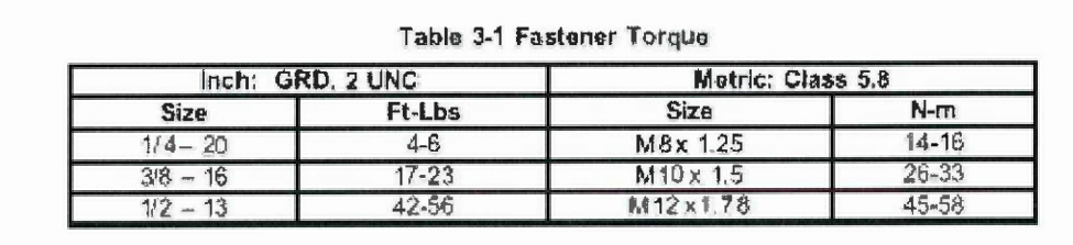
5.3.2.11 Fastening torques will be applied to carriage bolts in accordance with NEMA VE2 table 3-1.
5.3.2.12 Cable trays will be identified my stencil according to the noise susceptibility levels e.g. NSL 1 of the circuits going inside the cable trays.
5.3.2.13 Cable tray covers will be installed using approved hardwares after all the cables are installed, inspected and tested.
5.3.3 Conduit Installation.
5.3.3.1 Installation of conduits will be performed by skilled personnel in accordance with the applicable standards.
5.3.3.2 Conduit installed inside buildings will be installed at right angles and parallel to building walls using approved means of support.
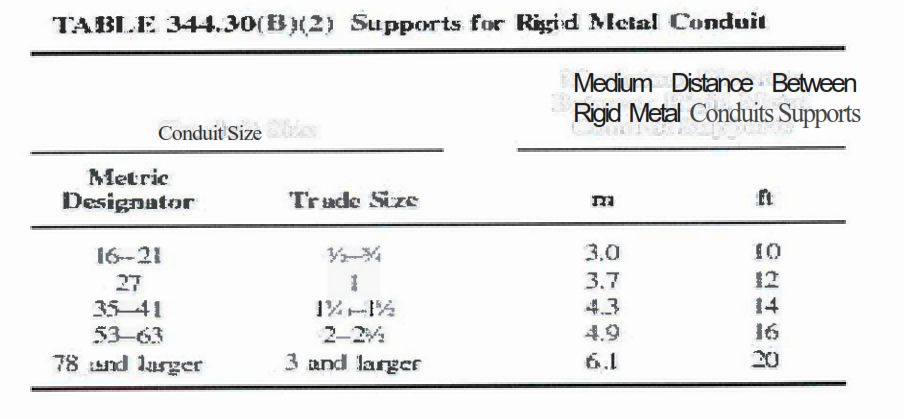
5.3.3.3 Supports will be installed at intervals in accordance with NFPA 70 Table 344.30 (8) (2).
5.3.3.4 Low point drain fittings requirement per NEC 225.22 when raceways are installed on exterior surfaces of building or other structures.
5.3.3.5 All field cuts will be smoothened using round-cut file or other suitable means to remove burrs and then touched-up using zinc-rich coating to prevent rust or corrosion.
5.3.3.6 All connections will be accomplished using fittings and accessories listed for the purpose.
5.3.3.7 Conduits terminating on cable trays and enclosures will be secured by locknut outside the cable tray and grounding type bushing inside to protect the cables from damage when pulling.
5.3.3.8 Conduits will be connected to ground at both ends using grounding type bushings. Where conduits terminate in on cable trays/enclosures, the end at the point of
termination will be bonded to the cable trays/enclosures.
5.3.3.9 Where flexibility is required after installation, liquid-tight flexible metal conduit will be used. Sizes, securing and supporting of LFMC will be in accordance with NFPA 70 section 350.30 (A) and (8) and NEMA RV 3.
5.3.3.10A bonding jumper will be installed along the flexible conduit to ensure electrical continuity.
5.3.3.11 For severe corrosive locations as defined by SAES, hot-dip galvanized rigid steel PVC-coated conduit will be used.
5.3.3.12Where rigid steel conduits are used in hazardous locations to connect with flameproof (Ex d or Aex d), a conduit seal fitting with sealing compound will be used to prevent pressure piling in the event of explosion inside the enclosure. Alternatively, cable glands suitable for the area classification i.e. Class, division, zone, gas group and temperature class may be used.
5.3.3.13 After cable pulling and inspection, all conduit bodies, junction boxes and pull boxes will be covered.
5.3.3.14 Conduits will be labeled with respective cable tag numbers at both ends using stainless bands secured with cable ties.
5.3.4 Cable laying, Testing & Termination
5.3.4.1 Cables will be tested for continuity and insulation resistance for l minute after being laid on cable trays or in conduits. For instrument cables rated 300V, the test voltage will be 500VDC.
5.3.4.2 When laying cables in cable tray or conduits, the drum will be placed on the cable jack and rolled in the direction shown on the drum to avoid twisting.
5.3.4.3 Cable tray percentage fill will be as per Article 392 of NEC.
5.3.4.4 Conduit percentage fill will be as per NEC Chapter 9 Table l:
5.3.4.5 Cables installed in cable trays will be dressed properly using approved cable ties taking consideration of the destination of the cables to avoid crossing or overlapping.
5.3.4.6 Stainless cable tags will be placed at regular intervals and at every change in direction and before & after wall penetrations.
5.3.4.7 After cable installation, continuity and insulation resistance test will be carried out to make sure that the cables are not damaged during installation
and to ensure that the cables goes to the correct destination as per cable routing layout, cable schedule and termination diagrams.
5.3.4.8 Cables will be terminated with the use of approved terminal blocks (DIN rail terminal blocks, cable lugs) appropriate for the size of the cables.
5.3.4.9 Core markers of approved type will be placed on each wire showing the source/destination terminals as per SAES-J-902 for instrument and SAES-P-104 for power and electrical controls.
5.3.4.10 Spare wires will have additional core marker indicating “SPARE” separate from the source/destination markers.
5.3.4.11 All shields will be covered with green shrinkable sleeve and terminated on the instrument ground bus bar provided in the DOC. Field end of the shields will not be terminated.
5.4 PRE-COMMISSIONING
Consist of various activities/records which are carried out after equipment erection, prior to energization and performance checks including the associated equipments/devices. It is therefore concerned with the verification of the state of readiness, system integrity, quality and compliance with project standards.
5.4.1 The following shall be verified after installation and tests had been carried out with the equipment prior to energization.
5.4.2 All cable/wire continuity shall be checked to ensure correct termination and identifications.
5 .4.3 Insulation tests of all cables/wires shall be completed and documented.
5.4.4 All cables/wires’ termination and identification is completed and documented.
5.4.5 After completion, all wiring termination connection shall be verified as per IFC drawings.
5.4.6 Ensure all the instrument control cabinets & panels including all associated devices have the required inspection reports.
5 .4. 7 Ensure all the required cable/conduit sealing installation shall be completed/inspected with regards to vendor’s instructions after loop functional performance check.
6.0 TOOLS AND EQUIPMENTS
6.1 Power tools.
6.2 Basic electrician hand tools.
6.3 Testing instruments with valid calibration certificate.
6.4 Cable trays and conduits cutting & fitting tools.
6.5 Access ladders/ scaffolds.
6.6 Personal protective equipment.
6.7 Industrial type power cords.
6.8 Mobile generators (if power supply is not available at site).
6.9 Adequate ventilation and lighting equipment.
7.0 INSPECTION AND TEST
7.1 Factory acceptance tests if required in the ITP will be facilitated by the Vendor and witnessed by DEC and SA representatives. Field test reports shall be submitted to SA for review and acceptance.
7.2 Work execution, material approval and test shall be monitored, witnessed and recorded according to the sequence of inspection as per ITP.
7.3 Inspection and tests shall be as per ITP procedure.
8.0 QUALITY CONTROL
8.1 Inspection and Test Plan (ITP) pertaining to Electrical installation work shall detail necessary inspection requirements and shall be submitted to OWNER’S ENGINEER REPRESENTATIVE for review and approval
8.2 Request for inspection (RF!) of works shall be issued to CONTRACTOR and OWNER’S ENGINEER REPRESENTATIVE 24 hours in advance for carrying out inspection in a feasible manner and to avoid delay in the inspection.
8.3 Upon completion of inspection, relevant inspection report as specified in ITP shall be signed and accepted.
9.0 SAFETY
9.1 All the construction personnel involved directly in HVAC instrumentation installation activities shall receive safety orientation/training prior to work at site.
9.2 Warning signboards and barricades shall be provided where necessary to isolate the working area and prevent unauthorized personnel from entering the site.
9.3 All electrical equipments shall be tagged and checked before using.
9.4 In case of extended working hours after daylight, sufficient lighting and welfare facilities shall be made available at site.
9.5 Appropriate work permit system shall be followed during the construction activities werein HSE requirements are fulfilled as specified in Work Permit.
9.6 Housekeeping must be strictly observed at all times during the entire works.
10.0 DOCUMENTATION
10.1 This method statement is a controlled document and will be properly be distributed to its responsible department involved in the execution prior to commencement of the works.
10.2 Inspection required shall be kept and maintained according to the approved quality plan.
10.3 Correspondence and designed documents such as drawings, design and specifications shall be managed properly.
10.4 Records are corrected after they are reviewed by the originated organization.
11. JOB SAFETY ANALYSIS FOR HVAC ELECTRICAL INSTALLATION