1 PURPOSE
2. SCOPE
3. REFERENCES
4. RESPONSIBILITY
5 MANPOWER CATEGORY
6. REQUIRED TOOLS
7 METHODOLOGY
8. QUALITY CONTROL AND ASSURANCE
9. SAFETY INSTRUCTIONS & PRECAUTIONS
10. ATTACHMENTS
1.0 PURPOSE
The purpose of this Method Statement will serve as a minimum guidelines to carry out the Installation of Overhead Crane. This procedure will provide necessary requirements and responsibilities relating to the installation, inspection and test of Overhead Cranes for Compressor Shelters. This specification gives a set of recommendations allowing the realization of mounting and fastening of a crane track on girders.
2.0 SCOPE
2.1 This method statement will cover the installation works of Overhead Cranes for Compressor Shelter area, etc. in accordance with applicable codes, standards for plants and refineries.
3.0 REFERENCES
3.1 Specification and Standards
3.1.1 S-000-1520-101 Field QC Procedure
3.1.2 S-000-1650-001 Safety Execution Plan
3.13 S000-1351-002 Installation Marking Procedure
3.1.4 S-000-3150-001 Installation of Static Equipment
3.1.5 FWBS CODE (5000) Equipment Installation
3.1.6 S-000-1520-103 Handling Procedure
317 S000-1630-003 Material & Equipment Protection Program at work site
3.2 ARAMCO Specification and Standards
3.2.1 SAES-B-014 Safety Requirement for Plant and Operations Support Buildings.
3.2.2 SAES-M-001 Structural Design for Non-Building Structure.
3.2.3 12-SAMSS-008 Erection of Structural and Miscellaneous Steel.
3.2.7 SCHEDULE Q Saudi ARAMCO Project Quality Requirements.
3.2.8 Saudi ARAMCO Safety Requirements for Scaffolds.
3.2.9 Saudi ARAMCO Construction Safety Manual.
3.2.10 Related Vendors Installation and Maintenance Manuals and Specifications.
3.2.11 SAES-P-100 Basic Power System Design Criteria.
3.2.12 SAES-B-053 Machine Safety Guarding, Elevator, Escalator & Conveyors.
3.2.13 SAES-P-104 Wiring Methods & Materials.
3.2.14 SATIP-P-113-04 Crane< Hoist and Elevators.
3.3 Industry Codes and Standards
1.3.1 Steel Design Guide for Baseplate and Anchor Rod Design.
1.3.2 AWS 01 .1 Structural Welding Code.
1.3.3 PIP STS05130 Erection of Stnuctural and Miscellaneous Steel Specification.
3.4 Inspection and Test Plan/ Method Statement.
3.4.1 SATIP-M-001-01 Structural Steel- Pipe rack, Steel Supports & Miscellaneous Steel Structures.
4.0 RESPONSIBILITY
Site Manager
Ensure full compliance by all Millwrights, Mechanical Foreman, Electrician and Labor regarding
execution of work and implementation of HSE procedure in accordance with project requirement and
specifications Confirm availability of all materials, tools, equipment and required personnel who will
carry out the work.
Quality Control Inspector
Conduct inspection in accordance with this procedure. Monitor daily activities and verify compliance to
ARAMCO Specifications. Prepares record and final acceptance documentation where required.
Construction Manager
a. Pre-mobilization Inspection and color coding for all tools and equipment used on site. Ensure that all safety requirements have been adequately addressed and the work is carried out in accordance with ARAMCO project safety procedures.
b. Ensure relevant documentation and certifications are submitted for operators, drivers, scaffolding and rigging.
Mechanical Supervisor
Prepare and submit method statement for review and approval. Provide latest revision of OHC drawings, procedures, material specifications standards and technical specifications. Provide latest as built drawings for every receive equipment.
Rigging Supervisor
To ensure that rigging and heavy lift activities are performed by SAUDI ARAMCO certified rigger in a safe and efficient manner. Rigging is engineered, performed and inspected to satisfy the customer’s requirements in accordance with the issued project drawings and specifications.
Safety Officer
Check the work areas and monitor from time to time in the implementation of safety procedure and assuring that all safety equipment and tools are present at site and in good working condition.
5.0 MANPOWER CATEGORY
5.1 Foreman
5.2 Welder
5.3 Mechanical Fitter
5.4 Fabricator
5.5 Helper
5.6 Scaffolder
5.7 Surveyor
5.8 Rigger
5.9 Electrician
5.10 Permit Receiver and other involved Manpower
6.0 REQUIRED TOOLS
6.1 Appropriate Crane for Specified Lift
6.2 Slings/Non Metallic Ropes/Soft Tag Lines
6.3 Shackles/Seam Clamps
6.4 Spreader Beam or Frame/Chain Hoist
6.5 Welding Machine for Tacking of Liners/Wedges
6.6 Wrenches/Leveling Tools/Feelers and Dial Gauges
6.7 Precision Levels/Calibrated Gauge/Torque Wrench/Hand Tools
6.8 Equipment/Survey Equipment
6.9 Equipment shall be maintained and checked prior to use for safe work assurance
6.10 Equipment shall be approved and certified by SAUDI ARAMCO
6.11 All tools must be calibrated before using
7.0 METHOD STATEMENT FOR INSTALLATION OF OVERHEAD CRANE
7.1 Prepare necessary work permit prior to conduct the activity.
7.2 Prepare all tools and equipment needed during installation.
7.3 Provide scaffolding access prior to installation and alignment of crane runway rail & girder.
7.4 Offloading of Rail
7.4.1 Rail will be off loaded by Mobile Crane
7.4.2 Rails to be lifted in banded bundles. Lifting chains to be double wrapped around rail bundle. Good communication between fork truck driver and slinger/signaler must be maintained at all times.
7.4.3 Rails to be lifted from lorry and lowered onto wooden bearers at floor level in designated storage area. A minimum of three wooden bearers to be used per rail length.
7.5 Installation and Assembly
7.5.1 Precaution before installation
1. After executing the installation of rail support structure, crane rails shall be
installed before the roof of shelter is covered.
2. Cranes shall be assembled and installed in accordance with approved installation
drawing and manufacturer’s instruction. See attached (INSTALLATION, DESIGN AND MAINTENANCE OF OVERHEAD CRANE)
3. Lugs and lifting parts shall be visually checked for defects such as crack, deflection, improper welding and poor materials prior to start the work.
4. Cranes before the installation shall be firmly fixed after structure supports and runway rail are aligned.
5. Crane components or temporary disassembled parts while shipping shall be assembled in accordance with manufacturer’s drawing. See attached (V-2155501-4-820)
6. Bolt tightening shall be performed in accordance with manufacturer’s instruction and specified torque value in drawing. If there is no specified torque value, snug tightening is then required.
7. Crane girders have to be clean and free from every grease oil, painting, calamine waste, etc.
7.5.2 Installation of Runway Girder, Runway Rail and End Stoppers
1. After finishing the installation of rail support structures, crane rails shall be installed in accordance with drawing and manufacturer’s instruction. See (V-2155 501-A-820) and runway girders shall be fixed firmly.
2. Align rails cross section with centerline of runway girders.
3. Assemble the rails with fastening bolts. Smooth driving condition shall be achieved by accurately aligning the elevation of each rail.
4. Rail shall be seated on runway girders. Check that no rail junction is corresponding to a clip position. The minimum distance between any joint and an expansion joint shall be as per project specification/Engineers requirements. If necessary cut the rail.
5. Shim plates shall be used to adjust the elevation of the runway rails under the runway girders. Shims shall be smooth and free of foreign material including rust and shall be lightly lubricated before final assembly. When shims thickness is equal to or greater than 1.5mm, no more than three shim pieces shall be used between each runway girder and girder bracket. Shim plate installation shall be followed according to the manufacturer’s recommendations. The shims material shall be stainless steel unless otherwise noted on the manufacturer’s instruction.
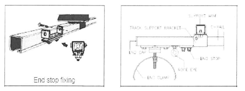
6. Install the end stoppers at the end of crane runway. The front edges of the end stops must be flush with each other and be at right angles to the crane runway.

7. Rail welding shall be accordance with WPS (DEC-WPS-AWS-01). Protect the girder during welding from excess of heat.
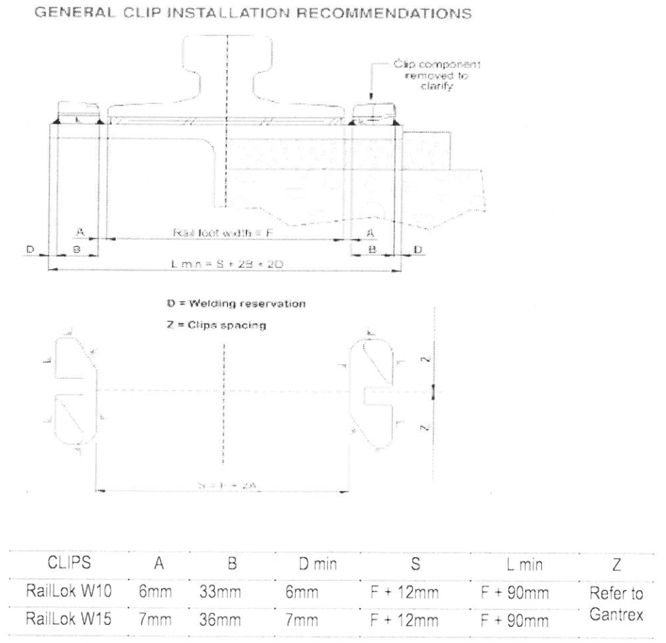
7.5.3 Installation and Welding of Runway Rail Clips
8. The centerline of the rail must be used as the reference. Identify the theoretical axis of the rail using piano wire, laser beam or other equipment
9 Clips should be installed in opposing pairs. They should never be staggered.
10. Clip installation sequence
a. Install the bolt heads in the clips lowers and push as far as possible
b. Install the clip upper part and push it against the rail
c. Install the nuts and finger tight
d. Once the clip upper part is in position, use an impact wrench to torque the nut,
while holding the upper in place.
11. Welding should be completed prior to pad installation as excessive heat could damage the pad.
12. Welding shall be conducted in accordance with ARAMCO standard unless otherwise specified by special requirements in drawing or manufacturers instruction.
13. Welding of clip’s lower part shall be followed in accordance with WPS (DEC-WPS AWS-01).
14. Do not paint between clip components unless approved by QC/PIO 15. Clip spacing, distance of weld to the edge of the steel plate, as well as corrosion protection will depend on application; otherwise consult to vendor’s manufacturers.
16. Gap between crane rails and rail lower clip shall be assembled in accordance with manufacturer’s recommendation. See (V-2155-501-4-820).
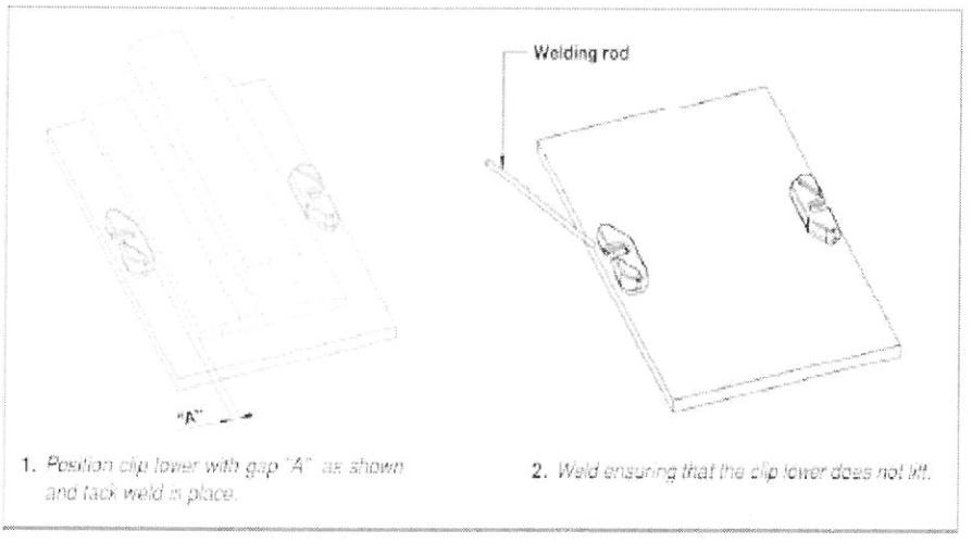
17 After proper spacing of rail clip to runway rail, tack welds the clip on both ends and in the middle. The lower components of the clips are welded to the support structure. The actual weld size is dictated by design thrust and should be specified by the vendor drawing. Verify again the gap between rail clip and runway rail after tack welding with the approval of QC inspector. Then proceed to final welding. Weld type shall be accordance to vendor drawing.
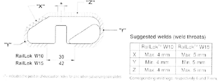
a. Weld “Y” on the back and sides of the clip may be as large as required to accommodate the imposed side thrust and to meet governing code requirements.
b. Welds “X” &Z on the side facing the rail may not exceed the indicated values. This will avoid any interference with the locating lug on the upper component or the rail.
c. Weld Z on the side along the rail is not applicable if no pad is used The foot of the rail may touch the weld. If the weld size or lengths are reduced, the full capacity of the clip might be jeopardized.
INSTRUCTIONS FOR CORRECT POSITIONING AND WELDING
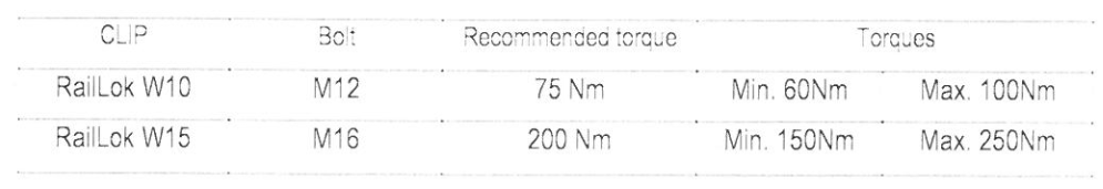
18. Bolt torqueing for rail clips shall be performed in accordance with manufacturer’s
instruction. See (INSTALLATION, DESIGN AND MAINTENANCE OF OVERHEAD CRANE)
7.5.4 Bridge Girder
1. Installation points of the end truck shall be marked on the runway rails.
2. End truck shall be install on the runway rails, then check the alignment.
3. Bridge girder shall be installed and assembled at the end truck
4. Check and record the diagonal distance of trolley rails.
7.5.5 Trolley Install a trolley on the bridge girder in accordance with drawing provided by the manufacturer.
1. Check any obstacles or interference during trolley lifting work.
2. Wire ropes and hooks shall be installed in accordance with the manufacturer’s instruction.
7.5.6 Assembly of Power Supply to Trolley & Electrical Equipment.
1. The trolley and pendent festoon systems are fixed to the suspension bracket which are clamped or plugged to the crane girder.
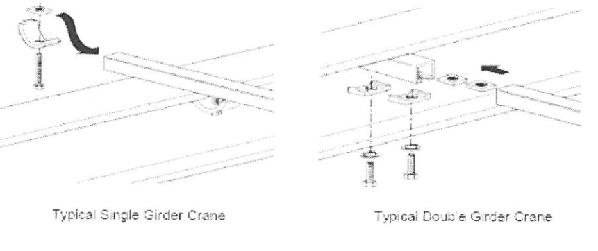
2. Hoist unit of single girder cranes will always be dispatched duly assemble with girder. For double girder cranes dispatched in dis assembled condition, after assembling the end carriages and festoon system, place the hoist unit over the trolley rail welded to the girder. Fix the towing arm trolley.
3. Electrical installation shall be refer to electrical drawings.
4. Installation of Crane Power line Crane power supply must be arranged or protected in such a way that they cannot be touched by the load bearing parts even if the load swings.
5. Installation of End carriages shall be assembled with the girders on the ground before raising ii up.
6. Installation of Festoon power line. Refer to the vendor drawing arrangement.
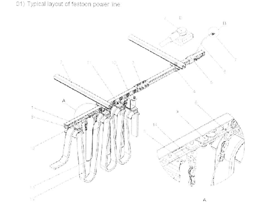
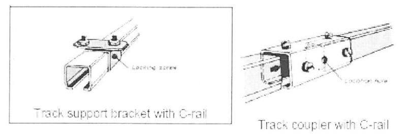
a. Installation of support arm on runway for Cranes. The support arms shall be fitted to the top of runway using Girder clips or fitted to the bottom or runway top flange using Weldable bracket.

b. The track support brackets shall be mounted to the support arm. Track couplier is slipped halfway onto the first joint of the C rail and then clamped
c Mounting the components in the C Rail
d. Mounting of Cable

e. Grounding of C-rail

f. Towing arm is fixed to the crane end carriage.

g. Fixing of crane limit switch and actuators
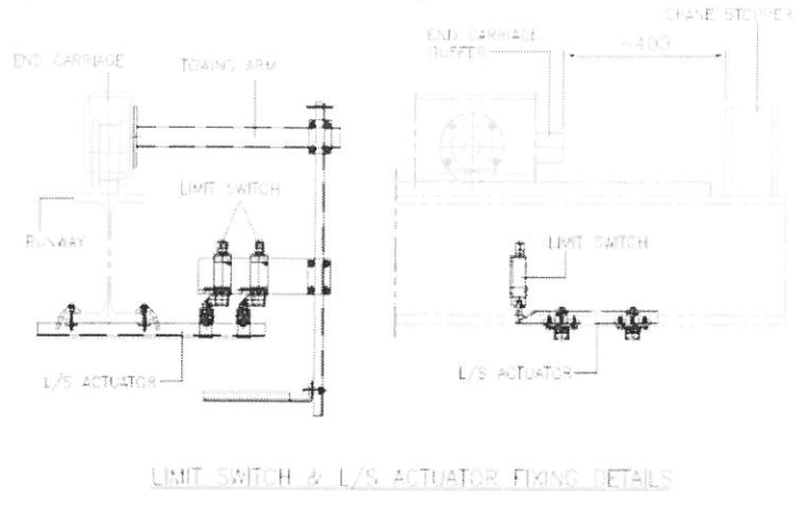
Crane limit switch is fixed to the power line pick up arm & the power line pick up arm is fixed to the end carriage.
7.6 Tolerance for Alignment of Rail
7.6.1 The maximum out of parallel horizontal alignment between rails on opposite sides of Crane track tolerances shall be as per Manual recommendation. See (INSTALLATION, DESIGN AND MAINTENANCE OF OVERHEAD CRANE). Check the dimensions and clearance of the runway with reference to General Arrangement drawing.
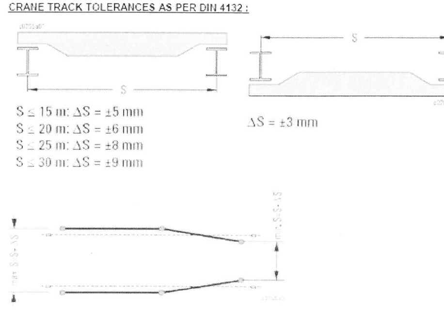
762 The maximum horizontal deviation from a specified straight line, from end to end of the total length of rails on each side of runway or at any point within the total length does not exceed ± 1 mm per 2m or otherwise specified by vendor’s manufacturer’s manual.

7.6.3 All rails shall be set level at the specified elevation within the maximum deviation of ±3mm.
7.6.4 Vertical alignment for runway rails shall be met the following requirements or the requirements of the crane supplier. Height variance between two rails shall be 0.15% of total span (max.10mm) between two rails.

7.6.5 Height difference or length unevenness for a rail should not exceed to ±1 mm per maximum length of 2 meter.

7.7 Painting work
7.7.1 Paint materials for each coating system shall conform to required manufacturer recommendation.
7.7.2 In case the girders are protected with a painting system, the following caution will have to be taken:
h. If the girder is treated before welding of crane, clips lower parts, only a weldable primer will be used.
• If the girder is treated after welding of crane clips lower part, the painting layer applied on the upper side of the lower part must not exceed 35m The upper side should be protected from any additional layers applied afterwards.
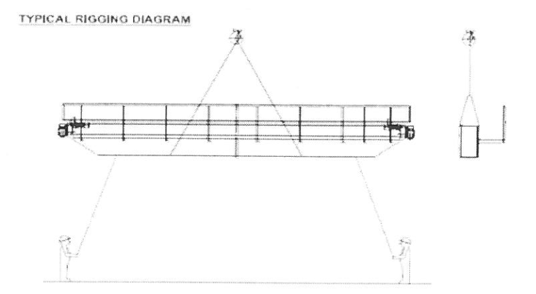
7.8 Erection of Overhead Crane
7.8.1 Lifting and Rigging of Equipment
7.8.1.1 Ensure all personnel and equipment to be utilized for the installation work are qualified and certified in accordance with SAUDI ARAMCO SAIC-D-2007 AND SATIP-D-001-01.
7.8.1.2 Provide the necessary protective materials such as wood softeners or equivalent to prevent any damage that may result from lifting.
7.8.1.3 Construction equipment, machine tools and calibrated measuring instruments to be used during removing shall be thoroughly inspected.
7.8.1.4 For lifting the crane, the use of a mobile crane is recommended.
7.8.1.5 Balance the crane and trolley/crab so that the crane hangs horizontal during lifting.
781.6 Secure trolley/crab against shifts while the crane is being lifted or is suspended in the air, the crane may fall and cause a fatal accident.
7.8.1.7 Lift the crane with guide ropes while lifting. Each rope must be guided by one person. Attach the guide ropes in such a way that the persons holding them are not standing underneath the load.
7.9 Preliminary No Load Test
7.9.1 All cranes newly installed shall be tested by designated or authorized inspector before initiate to use.
7.9.2 Load test shall be conducted by an experience and qualified operator.
7.9.3 Master switches and controllers shall be confirmed that they are in in neutral condition
7.9.4 Main power and control switches shall be connected for the test operation.
7 9.5 Initial no load test shall be performed to check normal operation.
7.10 Load Test Rated 100%
7101 The crane shall be statically loaded at mid-span to a maximum of 100% of hoist manufacturer’s rating and the deflection of the bridge at its center shall be measured and recorded.
7.10.2 With this load, crane shall be operated through all drives for hoist, trolley and bridge and through all speed ranges to demonstrate speed controls and proper function of limit switches, locking and safety devices.
7.10.3 Load Test Sequence
Reflecting the field condition, either 100% rated load test or 125% rated load test can be performed whichever or the two is prepared first. The order of each test can be changed.
1. Rated load of cranes shall be checked before the test, load block for the rated load test shall not be less than 100% of the rated load.
2. Master switches and controllers shall be confirmed that they are in neutral condition.
3. Test load blocks for the test shall be suspended at bottom block. At the same time, the load blocks for the test shall be in vertical position with bottom block to prevent from tilting.
4. Test load shall be uniformly distributed on slings or other lifting gears and the load test shall be conducted without any interference.
5. After performing the test for all operations, limit switch, control system brake, etc. shall be checked.
6. Subcontractors shall prepare blocks or frames for the load test.
8.0 QUALITY CONTROL AND ASSURANCE
8.1 Inspection shall be conducted and recorded
in accordance with the Job Specification Inspection and Test Plan.
9.0 SAFETY INSTRUCTIONS AND PRECAUTIONS
9.1 Make sure that all necessary work permits are issued.
9.2 Check all lifting equipment prior to commencing lifting activities.
9.3 Stay away from any suspended load/falling objects
9.4 Wear full body harness when working at elevated platform.
9.5 Install safety nets when necessary.
9.6 Ensure that barricades and warning signs are properly installed.
9.7 Ensure that there are no hazardous or combustible gases present in the work area.
9 8 Install flashing lights to traffic.
9.9 Copy of approved JSA to be maintained at work site by Work Supervisor. Conduct daily Tool Box Talk and discuss work methodology prior to commencement of work.
9.10 Implement and monitor safety instruction on site.
10.0 ATTACHMENTS
10.1 JSA (Job Safety Analysis)
102 WPS
10.3 Installation, Operation & Maintenance Manuals ( INSTALLATION, DESIGN AND MAINTENANCE OF OVERHEAD CRANE )