This article is about MODBUS Protocol, How Modbus Works? Function Codes – Modbus variants and Memory Area focusing to the engineers, technicians and supervisors. You will find lot of documents related to this article. Just navigate our website www.paktechpoint.com and find more articles.
What is Modbus Protocol?
Modbus is a widely used communication protocol in industrial automation and control systems. It was developed in the late 1970s and has since become one of the most popular protocols for connecting industrial devices and equipment. Here’s a brief overview of Modbus history:
Development and Early Years:
- 1979: Modbus was first introduced by Modicon, an American company that later became part of Schneider Electric. The name “Modbus” is a combination of “Modicon” and “bus,” referring to the communication system.
- 1980: Modbus was originally designed for use with Modicon programmable logic controllers (PLCs) and their associated devices. The protocol’s simplicity and ease of implementation made it popular in industrial applications.
The Modbus protocol is a communication protocol commonly used in industrial automation and control systems to enable communication between various devices, such as programmable logic controllers (PLCs), sensors, actuators, and other field devices. It provides a standardized way for these devices to exchange data, allowing for real-time monitoring, control, and coordination within industrial processes. Modbus was initially developed by Modicon (now part of Schneider Electric) in the late 1970s and has since become a widely adopted protocol in the industrial sector.
How Modbus Works?
- Request:
- The function code in the request specifies the action that the addressed slave device should perform.
- The data bytes provide any additional information required by the slave to carry out the function. For instance, function code 03 requests the slave to read holding registers and the data field must include the starting register address and the number of registers to read.
- The error check field ensures the integrity of the message contents, helping the slave validate the accuracy of the data.
- Response:
- In a normal response, the function code in the response mirrors the function code in the request.
- The data bytes in the response contain the collected data from the slave, such as the values of registers or status information.
- If an error occurs, the function code is altered to indicate an error response. The data bytes then contain an error code that describes the nature of the error.
- The error check field in the response allows the master to verify the validity of the message contents, adding another layer of data integrity check.
- Transmission Modes: ASCII and RTU:
- Modbus controllers can communicate on standard Modbus networks using two transmission modes: ASCII and RTU.
- ASCII mode involves encoding data in ASCII characters, while RTU mode uses binary encoding.
- Both modes have their advantages and use cases. ASCII is more human-readable, while RTU is more compact and faster due to its binary nature.
This provides a clear understanding of how Modbus messages are structured, how requests and responses are formatted, and the importance of function codes and error checking in ensuring accurate communication between master and slave devices.
Modbus variants
There are several variants of the Modbus protocol, each tailored for specific communication interfaces and requirements:
1. Modbus RTU (Remote Terminal Unit):
Modbus RTU is the most common variant and is used over serial communication interfaces like RS-232 and RS-485.
- It uses binary encoding to represent data, which allows for efficient transmission of information.
- Each data point is represented by a unique address, making it easy to identify and access specific devices and data.
2. Modbus ASCII:
- Modbus ASCII uses ASCII characters to represent data and is also used over serial communication interfaces.
- It’s less efficient compared to Modbus RTU due to the larger message size caused by ASCII encoding.
- Similar to Modbus RTU, each data point is assigned a unique address for communication.
3. Modbus TCP/IP:
Modbus TCP/IP is designed for communication over Ethernet networks, both local and wide area.
- It encapsulates Modbus RTU or Modbus ASCII messages within Ethernet frames, allowing for real-time communication and integration with modern network technologies.
- Modbus TCP/IP devices are identified by IP addresses, making network configuration crucial.
4. Modbus over Serial Line (RS-485/RS-232): Modbus can also operate over serial connections using RS-485 or RS-232 standards. It’s commonly used in scenarios where serial connections are preferred.
5. Modbus Plus: An older proprietary variant developed by Schneider Electric. It’s designed for high-speed communication and large-scale networks.
6. Modbus on CAN (Controller Area Network): Modbus can also be implemented over CAN networks, commonly used in automotive and industrial applications.
7. Modbus on Zigbee: Zigbee is a wireless communication protocol, and Modbus can be implemented over Zigbee networks for remote and wireless monitoring and control.
8. Modbus on PROFIBUS: Modbus communication can be integrated into PROFIBUS networks for interoperability between Modbus devices and PROFIBUS systems.
How Modbus Operates?
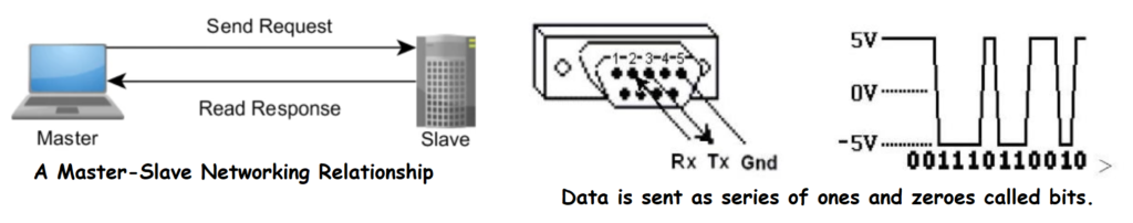
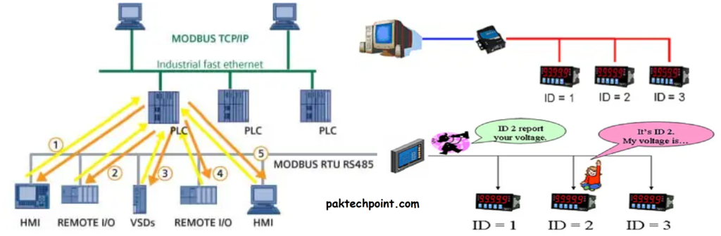
The Modbus protocol operates using a master-slave architecture:
- Master: The master device initiates communication and requests data from slave devices. It can also write data to slave devices for control purposes.
- Slave: Slave devices respond to requests from the master, providing the requested data or performing the specified action.
The protocol involves a set of standard function codes that define various types of data transactions, such as reading or writing registers, coils, or discrete inputs. These function codes determine the type of operation the master wants to perform on the slave device.
Modbus’ simplicity, ease of implementation, and widespread adoption have contributed to its continued relevance in industrial automation, especially in legacy systems and environments where more complex protocols may not be necessary. It’s important to note that while Modbus has been widely used, newer protocols like OPC UA and MQTT are emerging to address the requirements of modern industrial communication, particularly in the context of the Internet of Things (IoT) and Industry 4.0.
Modbus Protocol Data Unit
In the Modbus protocol, a Protocol Data Unit (PDU) refers to the portion of a message that contains the actual data being exchanged between the master and slave devices. The PDU encapsulates the command or response data, along with any associated parameters, function codes, and addressing information. The PDU does not include any headers, checksums, or control information related to the physical or data link layers.
The structure of a Modbus PDU varies depending on the specific variant of the protocol being used (Modbus RTU, Modbus ASCII, or Modbus TCP/IP). However, some common elements can be identified:
- Function Code: The function code is a key element of the PDU. It defines the type of operation the master wants to perform on the slave device, such as reading data, writing data, or performing specific actions. Different function codes indicate different types of Modbus transactions.
- Data Content: The data content of the PDU includes the specific information required for the requested operation. For example, if the master is requesting to read data from the slave device, the data content would include the starting address of the data to be read and the number of registers or coils to be retrieved.
- Error Codes: In case of an error, the PDU might include error codes that provide information about the nature of the error, allowing the master to understand the cause of the problem.
For Modbus RTU and Modbus ASCII, the PDU is embedded within the frame structure that includes the slave address, CRC (Cyclic Redundancy Check) or LRC (Longitudinal Redundancy Check), and other control information specific to the data link layer.
For Modbus TCP/IP, the PDU is carried within the payload of an Ethernet frame. The TCP/IP header includes information about the source and destination IP addresses and the specific TCP or UDP port numbers corresponding to Modbus communication.
Overall, the PDU is the essential part of a Modbus message that contains the actual data and instructions required for communication between the master and slave devices. Understanding the structure and content of the PDU is crucial for implementing, troubleshooting, and analyzing Modbus transactions.
Modbus Application Data Unit
The Modbus Application Data Unit (ADU) is a complete message that includes both the Protocol Data Unit (PDU) and additional information necessary for communication and error checking. The ADU encompasses the entire message, from the data link layer framing to the application layer data. It includes all the necessary elements to ensure proper communication between the master and slave devices.
The structure of the Modbus ADU differs depending on the specific Modbus variant being used:
- Modbus RTU and Modbus ASCII:
- In Modbus RTU and Modbus ASCII, the ADU consists of the PDU, followed by a Cyclic Redundancy Check (CRC) or Longitudinal Redundancy Check (LRC) value. The CRC or LRC is used for error checking to ensure the integrity of the message during transmission.
- The ADU also includes framing information specific to the data link layer, such as start and stop bits in the case of Modbus RTU.
- Modbus TCP/IP:
- In Modbus TCP/IP, the ADU is encapsulated within an Ethernet frame.
- The Ethernet frame includes source and destination IP addresses, as well as source and destination port numbers (typically Port 502 for Modbus).
- The TCP or UDP header is used to manage the reliability and flow control of the message.
- Within the payload of the Ethernet frame, the Modbus ADU contains the PDU and any associated data.
Overall, the Modbus ADU is a self-contained message that includes all the components needed for communication, error checking, and framing. It serves as the complete unit of information exchanged between the master and slave devices, encompassing the PDU and the necessary headers and checksums required for transmission and verification. Understanding the structure and content of the ADU is important for implementing and troubleshooting Modbus communication effectively.
Modbus New Function Codes
The Modbus protocol has a set of standardized function codes that define the types of operations that can be performed between the master and slave devices. These function codes specify whether the master wants to read data from the slave, write data to the slave, or perform specific actions. As of my last knowledge update in September 2021, the original Modbus function codes are well-established and widely used. However, new function codes might have been introduced since then.

Here are some of the common Modbus function codes:
- Read Coils (Function Code 01): Reads the status of discrete coils in the slave device.
- Read Discrete Inputs (Function Code 02): Reads the status of discrete inputs in the slave device.
- Read Holding Registers (Function Code 03): Reads the contents of holding registers in the slave device.
- Read Input Registers (Function Code 04): Reads the contents of input registers in the slave device.
- Function Code 5 (Force/Write Single Coil):
- Request includes the coil’s address and value to force/write (0 for off, FF00 for on).
- Normal response is the same as the request.
- Function Code 6 (Preset/Write Single Holding Register):
- Request includes the holding register’s address and the new value to write.
- Normal response is the same as the request.
- Read Exception Status (Function Code 07): Reads the status of exceptions (error conditions) in the slave device.
- Diagnostics (Function Code 08): Allows the master to perform diagnostic tests on the slave device.
- Get Comm Event Counter (Function Code 11): Retrieves the communication event counter of the slave device.
- Get Comm Event Log (Function Code 12): Retrieves the communication event log of the slave device.
- Function Code 15 (Force/Write Multiple Coils):
- Request includes the starting address, the number of coils, and the number of bytes of coil values.
- Coil values are in binary (0 for off, 1 for on) stored in 8 values per byte.
- Normal response includes the starting address and the number of coils.
- Function Code 16 (Preset/Write Multiple Holding Registers):
- Request includes the starting address, the number of holding registers, and the number of bytes of register values.
- Register values are included as new values in binary format.
- Normal response includes the starting address and the number of written holding registers.
These are just a few examples of the common Modbus function codes. However, the Modbus protocol might have evolved since my last update, and new function codes might have been introduced to accommodate changing industrial communication needs or to enhance the protocol’s capabilities. If you’re looking for the latest information on Modbus function codes, I recommend checking official Modbus documentation or resources from reputable sources.
Modbus Implementation on Network Layers
How the Modbus protocol can be implemented on different network layers, including UDP (User Datagram Protocol), in addition to its more common usage over serial communication and TCP/IP. Here’s a breakdown of the information:
- Modbus on Various Network Layers:
- Modbus is versatile and can be adapted to run on various network layers beyond serial and TCP. One potential implementation is using UDP.
- UDP Suitability for Modbus:
- UDP is well-suited for Modbus communication due to its simplicity and ability to send defined packets of information without additional application-level data.
- Simplicity of Modbus with UDP:
- Modbus being a message-based protocol fits well with UDP, as UDP allows sending packets without extra overhead like start characters or length information.
- Sending Modbus PDU with UDP:
- Modbus Protocol Data Unit (PDU) packets can be directly sent using a standard UDP API. This means that Modbus messages can be encapsulated within UDP packets and received as complete messages on the other end.
- Application Layer Acknowledgement:
- While TCP has built-in acknowledgment, Modbus handles acknowledgement at the application layer. This means that Modbus using UDP doesn’t require the same acknowledgement mechanisms as TCP.
- Elimination of Transaction Identifier in UDP:
- In TCP, the ADU (Application Data Unit) includes a transaction identifier field to manage multiple outstanding transactions. When using Modbus with UDP, this identifier field is not needed, simplifying the protocol.
- Synchronous Master or Identifier Usage:
- To manage requests and responses without the transaction identifier field, a synchronous master can be used. Alternatively, the UDP packet can include an identifier to help the master organize communication.
- Hybrid Implementation:
- The text suggests a hybrid approach where the Modbus TCP/IP ADU can be used on a UDP network layer. This retains the benefits of TCP’s acknowledgement while utilizing the simplicity of UDP.
This explanation highlights how Modbus can leverage the characteristics of UDP to create a streamlined and efficient communication setup, simplifying the implementation while allowing for organized communication between devices.
Modification of Application Data Unit
The provided text describes how an application can potentially modify an Application Data Unit (ADU), such as in the case of Modbus TCP, to accommodate additional information or parallel communication. Here’s a breakdown of the information:
- Modifying ADU for Custom Requirements:
- An application utilizing Modbus might choose to modify the structure of an ADU to meet specific requirements.
- Using Unutilized Portions of ADU:
- Certain fields in existing ADUs, like those in the Modbus TCP header, may be unutilized or carry fixed values that are not necessary for Modbus communication.
- Example: Modifying Modbus/TCP ADU:
- In Modbus/TCP, there’s a 16-bit length field, a 16-bit protocol field, and an 8-bit unit ID field.
- Given that the maximum Modbus PDU size is 253 bytes, the high byte of the length field is always zero since the maximum length is well below 65536.
- The protocol field and unit ID are often set to specific values (zero) in standard Modbus/TCP usage.
- Potential Modification Example: Sending Multiple Packets:
- The text suggests a potential extension of the protocol where three packets could be sent simultaneously.
- This could be achieved by repurposing the protocol field with a non-zero number to indicate the change.
- The two unused bytes (unit ID and high byte of the length field) can then be used to send the lengths of two additional PDUs.
This explanation outlines a scenario where an existing ADU structure, like Modbus TCP’s, could be repurposed or extended to accommodate additional data or parallel communication by utilizing unutilized fields or fixed values. However, such modifications should be carefully considered and implemented to ensure compatibility and interoperability with other devices and systems that adhere to the standard Modbus protocol.
MODBUS Memory Area
All programmable devices like PLCs, Remote terminal units and all loop controllers has memory. The memory in these devices used to store programme, data, backup and many other things. Now if the device has MODBUS compatibility it must has Modbus memory block area which is called Modbus memory area.
Now we will look at this memory area map in rectangle shape.

In which Coils and Inputs these areas consists of 1 bit memory block only. Input registers and holding registers consists of 16 bit memory block only. Coil has 1-10000 1bit memory area blocks and Discrete input 10001-20000 1bit memory area blocks. Like this input registers has 30001-40000 16 bit memory area block and holding registers have 40001-50000 16 bit memory area block. This is important points to remember because this memory coding is Modbus compliant.
But the question is that why we use these four areas memory block?
As we all know that Modbus is specially designed for PLCs to communicate each other and with other devices. PLCs has four field device connections with sensor or actuators.
1) Discrete Input or Input area (i.e Push button for ON and OFF).
2) Discrete Output or Coil Area (i.e Open or Close valve by actuators).
3)Analoge input or Input Registers( i.e Pressure and temperature transmittets).
4) Analoge Output or Output registers( i.e To control speed of VFD and Position of Control Valve).
Therefore there are four areas to control the four types of data.
Modbus Applications
Modbus protocol finds applications in various industries and scenarios due to its simplicity, versatility, and reliability. Some common Modbus applications include:
- Industrial Automation: Modbus is extensively used to control and monitor industrial processes, machinery, and equipment, connecting PLCs, sensors, actuators, and other devices.
- SCADA Systems: Modbus is often utilized as a communication protocol in SCADA (Supervisory Control and Data Acquisition) systems, enabling remote monitoring and control of distributed processes.
- Energy Management: Modbus helps manage energy consumption by connecting energy meters, monitoring power usage, and optimizing energy distribution in buildings and factories.
- HVAC Systems: Modbus is employed in heating, ventilation, and air conditioning (HVAC) systems to regulate temperature, humidity, and other environmental factors.
- Motor Control Centers: Modbus facilitates communication among motor starters, VFDs, soft starters, and other motor control devices, streamlining motor operation and protection.
- Building Automation: Modbus aids in controlling lighting, security systems, access control, and other building automation functions.
How to start communicating with your Modbus device?
To start communicating with your Modbus device, consider the following steps:
- Physical Connection:
Determine the type of Modbus protocol you’re using:
- Modbus RTU: Uses RS-485 or RS-232 for serial communication.
- Modbus TCP: Utilizes Ethernet for communication.
- Register Mapping:
Understand how the registers are organized and addressed in your Modbus device. This information is crucial for accessing and controlling specific data points.
- For gateways interfacing Modbus devices to non-Modbus networks, consult the equipment manufacturer’s documentation for register details.
- Control Solutions I/O devices usually provide this information in their help files or documentation.
- Communication Parameters:
For Modbus RTU:
- Define the baud rate, character format (e.g., 8 bits, no parity), and slave ID (unit number) correctly. Incorrect settings can lead to communication issues. For Modbus TCP:
- Determine IP addresses on the network. Some cases might require unit IDs.
Remember that:
- If using a Control Solutions gateway, choose the model that matches the electrical interface of your equipment.
- Modbus protocol doesn’t automatically identify registers; consult equipment documentation.
- Control Solutions I/O devices’ details can be found in their help files or on the manufacturer’s website.
- Verify communication parameters to ensure successful data exchange.
Keep these points in mind to establish effective communication with your Modbus device.
Devices Supported by Modbus
Modbus is supported by a wide range of industrial devices, including Programmable Logic Controllers (PLCs), Human-Machine Interfaces (HMIs), Remote Terminal Units (RTUs), Variable Frequency Drives (VFDs), sensors, actuators, energy meters, SCADA systems, and more. Its popularity makes it a common choice for communication and control in industrial automation and control systems.
Please read also: SYSTEM OVERVIEW AND CONTROL HARDWARE FOR COMPRESSOR CONTROL SYSTEM
Please read also: WHAT IS VFD AND ITS PRINCIPLE, WHY VFD IS USED
FAQs about Modbus Protocol
How can you send events and historical data?
Events:
Define event codes.
Use Modbus function codes to set designated coils/registers.
Query coils/registers for changes.
Historical Data:
Allocate registers or external storage for historical data.
Update data at intervals or triggers.
Respond to Modbus queries for retrieval.
Timestamps:
Include timestamps with data.
Communication Frequency:
Balance frequency with load and storage.
Data Format:
Choose suitable format (binary, ASCII, etc.).
nice article to learn basic and advance of modbus thanks