In the world of industrial automation and control, communication protocols play a crucial role in ensuring seamless data exchange between devices. Modbus RTU (Remote Terminal Unit) is one such protocol that has gained significant popularity due to its simplicity, efficiency, and versatility.
In this comprehensive guide, we will explain deep into the technical aspects of Modbus RTU, exploring its features, benefits, implementation, and more.

Understanding Modbus RTU
1. What is Modbus RTU?
Modbus RTU is a widely used communication protocol that facilitates data exchange between a master device (controller) and multiple slave devices (sensors, actuators) in industrial settings. RTU stands for Remote Terminal Unit, signifying its capability to control and monitor devices remotely. It operates on a master-slave architecture, where the master initiates communication and the slaves respond accordingly.
Modbus Remote Terminal Unit indeed follows a straightforward approach to data representation, making it easy to work with. The simplicity of its design is one of the reasons why Modbus has remained popular in industrial applications. The key points you mentioned can be summarized as follows:
Data Representation:
In Modbus RTU, data is represented with the least significant bit sent and received first. All devices on the network interpret bytes in this manner.
Baud Rates:
Modbus RTU does not include automated baud rate recognition. All devices on the network must use the same baud rate, typically set to 9600 or 19200. The protocol itself does not specify a particular baud rate.
Data Types:
Modbus Remote Terminal Unit has two primary data types: coils and registers. Coils are single bits that can be either ON (1) or OFF (0). They represent inputs or outputs in the system. Registers are 16-bit unsigned values, ranging from 0 to 65535 (0 to FFFF hexadecimal). Negative values and values beyond 65535 are not supported.
Input Registers and Holding Registers:
Input Registers and Holding Registers are the two main types of registers. Input Registers originally reflected analog input values, while Holding Registers were meant for temporary program storage. However, in modern devices, Input Registers function similarly to Holding Registers, serving as data storage.
Packet Content:
Modbus RTU packets are designed solely for data transmission. They lack the capability to transmit parameters like point names, resolution, units, etc. For more advanced features like parameter transmission, other protocols like BACnet or EtherNet/IP may be more suitable.
2. Modbus RTU vs. Other Modbus Variants
Modbus comes in various flavors, including Modbus RTU, Modbus ASCII, and Modbus TCP. Modbus RTU uses binary data representation, making it highly efficient for data transmission over serial communication links. In contrast, Modbus ASCII uses ASCII characters and is often slower due to character encoding overhead. Modbus TCP, on the other hand, uses Ethernet for communication, allowing higher data rates and longer distances.
Modbus RTU Frame Structure
1. Master-Slave Communication
In a Modbus RTU network, the master device initiates communication by sending requests to one or more slave devices. Each slave is assigned a unique address to identify them within the network. Upon receiving a request, the addressed slave processes the request and sends a response back to the master.
2. Addressing Scheme
Modbus Remote Terminal Unit supports up to 247 slave addresses, allowing a single master to communicate with a large number of devices. The addressing scheme is essential for routing requests to the appropriate slave device. The address space ranges from 1 to 247, with 0 reserved for broadcast communication.
3. Function Codes
Function codes define the type of operation to be performed by the slave in response to a master’s request. Some common function codes include:
- Read Coil Status (Function Code 1)
- Read Input Status (Function Code 2)
- Read Holding Registers (Function Code 3)
- Write Single Coil (Function Code 5)
- Write Single Register (Function Code 6)
Physical Layer and Communication
In the world of industrial automation, reliable communication between devices is essential. The physical layer forms the foundation of communication protocols like Modbus Remote Terminal Unit. Let’s delve into some key aspects of the physical layer in Modbus RTU networks.
1. RS-485 Interface
Modbus RTU is commonly implemented using the RS-485 interface, which is well-suited for industrial environments. RS-485 is a balanced differential signaling standard that allows communication over long distances while minimizing electromagnetic interference. It supports multidrop communication, allowing multiple devices to be connected on a single bus. This makes it suitable for scenarios where sensors, actuators, and controllers are distributed across a facility.
2. Data Transmission Modes
RS-485 supports two data transmission modes: full-duplex and half-duplex.
- Full-Duplex: In full-duplex mode, data can be transmitted and received simultaneously, allowing for faster communication. However, this mode requires separate transmit and receive lines for each device, which can increase wiring complexity.
- Half-Duplex: Half-duplex mode is more commonly used in Modbus RTU networks. In this mode, devices take turns transmitting and receiving data on the same communication line. While it reduces wiring complexity, it slightly slows down communication due to the alternating transmission.
3. Baud Rate and Data Bits
Configuring the baud rate and data bits is crucial for ensuring reliable data transmission in Modbus RTU networks.
- Baud Rate: The baud rate determines how quickly data is transmitted over the communication line. Common baud rates in Modbus Remote Terminal Unit networks range from 9600 to 115200 bits per second (bps). Selecting an appropriate baud rate depends on factors such as the distance between devices, the quality of cabling, and the noise environment. Higher baud rates allow for faster data exchange but might be susceptible to signal degradation over longer distances.
- Data Bits: Modbus RTU typically uses 8 data bits for transmission. Each data bit represents a binary value (0 or 1). Using 8 data bits provides sufficient data capacity to encode various types of information in the communication frame.
It’s important to note that the physical layer considerations in Modbus RTU networks significantly influence the overall performance and reliability of the communication. Proper cabling, shielding, and adherence to recommended baud rates ensure optimal data exchange and minimize the risk of communication errors.
In the next sections, we’ll explore the data format and communication flow in Modbus RTU networks, shedding light on how data is structured and exchanged between master and slave devices.
Modbus RTU Data Format
Understanding the data format used in Modbus Remote Terminal Unit communication is fundamental for configuring devices and interpreting data accurately. Let’s dive into the data format and its key components.
1. Binary Data Representation
Modbus RTU uses a binary data representation, where information is encoded as sequences of ones and zeros. This binary representation is the basis for transmitting data between master and slave devices in a Modbus network.
2. Frame Structure
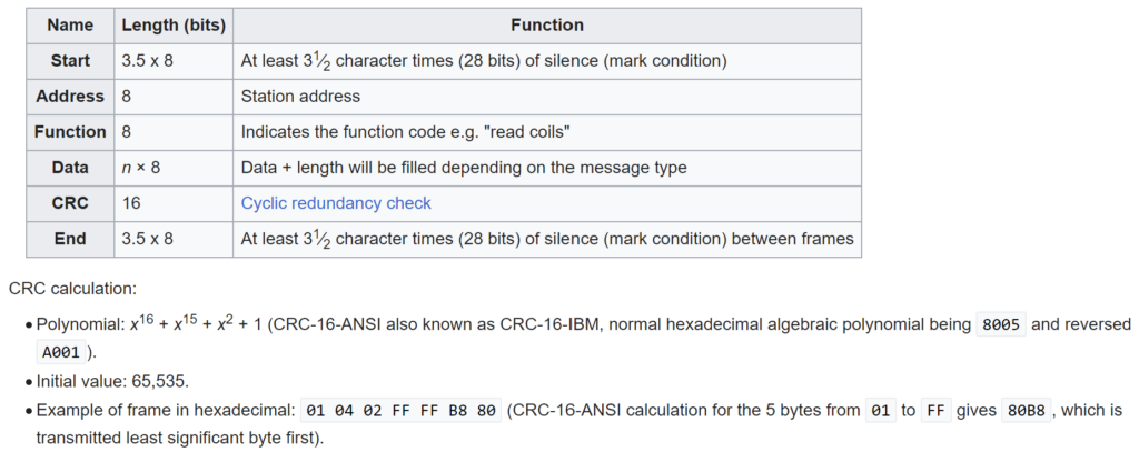
A Modbus RTU frame consists of several essential elements:
- Slave Address: Each slave device on the network is assigned a unique address. The master device uses this address to specify which slave it intends to communicate with.
- Function Code: The function code indicates the type of action the master device wants the slave to perform. It specifies whether the master is requesting data, writing data, or performing other operations.
- Data: The data field contains the actual information being transmitted. The format of the data depends on the function code. For example, if the master requests data, the data field might contain the values of registers read from the slave.
- Error Check: To ensure data integrity, Modbus RTU includes an error check field. This field uses a cyclic redundancy check (CRC) algorithm to detect any errors in the transmitted data.

3. Little-Endian vs. Big-Endian
Modbus RTU uses the little-endian format for data representation. In little-endian, the least significant byte of a multi-byte value is stored at the lowest memory address, while the most significant byte is stored at a higher memory address. This format aligns with the way that data is typically transmitted over serial communication lines.
For example, if a 16-bit value “ABCD” is transmitted in Modbus Remote Terminal Unit, it will be sent as CD (least significant byte) followed by AB (most significant byte).
4. Byte Ordering
It’s important to note that when interpreting data in Modbus RTU, especially for multi-byte values like 32-bit integers or floating-point numbers, you need to consider the byte ordering. The little-endian format used in Modbus RTU might differ from other formats, like big-endian, which stores the most significant byte at the lowest memory address.
Understanding the data format and byte ordering is essential when configuring and programming devices in a Modbus Remote Terminal Units network. Proper interpretation ensures that data is accurately exchanged between master and slave devices, preventing errors and inconsistencies in communication.
In the subsequent sections, we’ll explore how Modbus RTU communication is initiated, the role of master and slave devices, and the communication flow between them. This knowledge is crucial for setting up and managing Modbus networks effectively.
Modbus RTU Communication Flow
1. Request-Response Mechanism
Communication in Modbus RTU follows a simple request-response mechanism. The master sends a request packet containing the slave address, function code, and additional data such as register addresses or values to be written. The addressed slave processes the request and responds with a packet containing the requested data or an acknowledgment.
2. Exception Responses
In some cases, the slave may encounter an error while processing a request. In such situations, the slave responds with an exception response, indicating the type of error that occurred. Exception responses provide valuable diagnostic information to the master, helping in troubleshooting.
Benefits of Modbus RTU
1. Simplicity and Efficiency
Modbus RTU’s binary data format and compact frame structure make it highly efficient for data transmission. Its simplicity contributes to its widespread adoption in industrial environments.
2. Real-Time Communication
Modbus Remote Terminal Unit is well-suited for real-time applications where timely data exchange is crucial. Its low overhead and predictable response times make it suitable for time-sensitive processes.
3. Scalability and Versatility
With support for multiple slave devices and various function codes, Modbus RTU networks can be scaled to accommodate diverse industrial scenarios. Its versatility enables it to handle both simple and complex tasks.
Implementing Modbus RTU
1. Modbus RTU Master Configuration
Configuring a Modbus RTU master involves setting communication parameters such as baud rate, data bits, and stop bits. The master sends requests to slaves and processes their responses.
2. Modbus RTU Slave Configuration
In a Modbus RTU slave, the device’s address, function codes supported, and register mappings need to be configured. Slaves respond to master requests and provide the requested data.
3. Interfacing with Sensors and Actuators
Modbus RTU is commonly used to interface with a wide range of industrial devices, including sensors, actuators, motor drives, and more. These devices communicate data to the master for control and monitoring purposes.
Modbus RTU Error Handling
1. CRC Checksum
Modbus RTU uses a cyclic redundancy checksum to ensure data integrity during transmission. The CRC value is calculated by both the master and the slave, and any mismatch indicates a transmission error.
2. Error Codes and Diagnostics
In addition to the CRC checksum, Modbus RTU defines specific error codes to indicate various types of errors. These codes help diagnose communication problems and facilitate troubleshooting.
Security Considerations
1. Securing Modbus RTU Networks
While Modbus RTU doesn’t provide built-in encryption or authentication, network security measures such as firewalls, VPNs, and secure protocols can be employed to protect against unauthorized access.
2. Access Control and Authentication
Implementing access controls and requiring user authentication adds an extra layer of security to Modbus RTU networks. This prevents unauthorized devices from accessing critical data.
Modbus RTU in Industrial Applications
1. PLC Communication
Modbus RTU is extensively used for communication between programmable logic controllers (PLCs) and various industrial devices. It enables centralized control and monitoring of complex processes.
2. SCADA Systems Integration
Supervisory Control and Data Acquisition (SCADA) systems often rely on Modbus RTU for collecting data from remote field devices. The protocol’s efficiency and reliability are advantageous in large-scale deployments.
3. Process Monitoring and Control
Modbus Remote Terminal Unit plays a vital role in monitoring and controlling processes such as temperature regulation, motor control, and data acquisition in industrial settings.
Understanding Modbus RTU Communication
Modbus RTU, or Remote Terminal Unit, is a widely used protocol for communication between industrial devices. It offers a reliable and efficient way to exchange data in industrial automation systems. In this section, we’ll delve deeper into the Modbus RTU Application Data Unit (ADU) and explore its key components and challenges.
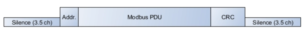
1. Simplicity of RTU ADU
The Modbus RTU ADU appears simpler than its TCP/IP counterpart. It consists of the core Protocol Data Unit (PDU) along with two additional pieces of information: the slave address and the cyclic redundancy check (CRC). This streamlined structure makes Modbus RTU suitable for serial communication, where efficiency and reliability are paramount.
2. Slave Address and Broadcast
The slave address plays a vital role in Modbus RTU communication. It designates which slave device the PDU is intended for. Remarkably, an address of 0 serves as the “broadcast” address. In this scenario, a master device sends a command to address 0, prompting all slaves to process the request without responding. This feature allows for simultaneous commands across multiple slaves without overwhelming the network.
3. Integrity through CRC
To ensure data integrity during transmission, Modbus RTU employs a cyclic redundancy check (CRC). The CRC is a mathematical algorithm that generates a fixed-size code from the data being transmitted. At the receiving end, the CRC is recalculated from the received data, and if it matches the transmitted CRC, it signifies that the data arrived intact.
4. Silent Times and Modern Challenges
While the Modbus RTU ADU seems straightforward, modern implementations introduce challenges. Between packets, there are silent times, or periods of no communication on the bus. These silent times are essential for synchronization. However, modern technologies like USB-to-serial converter cables and faster baud rates complicate matters. USB-to-serial cables can introduce variable gaps in the data stream, confusing specification-compliant code into believing messages are corrupted.
5. Abstraction and Polling
Modern driver technologies abstract serial communication, often requiring a polling mechanism from the application code. Yet, polling too slowly results in poor performance, while polling too quickly leads to high CPU usage. To address these issues, experts recommend breaking the layer of abstraction between the Modbus PDU and the networking layer.
By interrogating the Modbus PDU packet, function codes and packet lengths can be determined. Armed with this information, longer time-outs can be used, accommodating transmission gaps. This approach enables application-level polling to occur at a more reasonable pace, mitigating performance and CPU usage challenges.
Troubleshooting Modbus RTU Networks
1. Network Analysis Tools
Various network analysis tools can help diagnose Modbus RTU communication issues. These tools analyze packet transmission, CRC calculations, and identify potential sources of errors.
2. Debugging Techniques
Troubleshooting Modbus RTU involves checking communication parameters, device configurations, and using diagnostic tools to identify and resolve issues systematically.
Future Trends and Evolutions
1. Modbus RTU Over TCP/IP
The convergence of Modbus RTU and TCP/IP networks offers benefits like remote access, integration with IIoT platforms, and enhanced data analytics capabilities.
2. IIoT Integration
Integrating Modbus RTU with Industrial Internet of Things (IIoT) platforms enables data-driven decision-making, predictive maintenance, and advanced analytics for improved operational efficiency.
Conclusion
Modbus RTU remains a cornerstone in industrial communication due to its simplicity, efficiency, and widespread support. As industries continue to evolve, Modbus Remote Terminal Unit adapts by integrating with modern technologies, ensuring its relevance in the ever-changing landscape of industrial automation. By understanding the technical intricacies of Modbus RTU, engineers and professionals can harness its power to optimize processes, enhance control, and drive industrial innovation forward.
FAQs about Modbus RTU
What is the difference between Modbus ASCII and Modbus RTU?
Can multiple gateways act as masters on the same Modbus Remote Terminal Unit network?
As you mentioned, if you need to interface multiple devices that use different protocols or networks with Modbus Remote Terminal Unit devices, those gateways should be configured as slaves. They can respond to commands from the single Modbus RTU master and act as bridges to their respective networks.
Read Also: Modbus Protocol – How Modbus Works? Function Codes – Modbus variants