This article is for the design, basic concept and testing of 600 V class motor control centers (MCC) to be installed indoors in non-hazardous areas. Main keywords for this article are Motor Control Center Design Guide, Motor Control Center Layout, MCC Schematic Diagram, Motor Control Center Wiring Diagram, MCC Panel Components.

MCC References
National Electrical Manufacturer’s Association (NEMA)
ICS 1 General Standards for Industrial Controls
ICS 2 Standard for Industrial Control Devices, Controllers and Assemblies
UL 489 Molded Case Circuit Breakers and Circuit Breaker Enclosures
National Electrical Code (NEC)
Article 450-3(b)
Underwriters’ Laboratories (UL)
489 Molded Case Circuit Breakers and Circuit Breaker Enclosures
845 Motor Control Centers
Motor Control Center Design Guide 600V As Per NEC
The grouping of motor starters of the same operating voltage into modular, self contained MCC‟s shall be the preferred configuration.
MCC shall be configured and wired as detailed in NEMA ICS 2.
MCC shall comply with the provisions of UL 845. Measurements shall be in SI units.
All units shall be accessible, interchangeable to the same size, and removable from the front of the MCC. Rated voltage and current for MCC shall be based on 60 Hz or 50 Hz.
Motor Control Center Layout

MCC Schematic Diagram

Main keywords for this article are Motor Control Center Design Guide, Motor Control Center Layout, MCC Schematic Diagram, Motor Control Center Wiring Diagram, MCC Panel Components.

Motor Control Center Wiring Diagram
MCC Structural Requirements
Common Enclosure and Cubicle Design
- The vertical sections of MCC shall consist of one or more standardized sections, bolted together to form a rigid, self-supporting, free-standing assembly, with capability for addition of further sections to either end.
- Each vertical section shall be isolated from adjacent sections by steel barriers.
- MCC shall have easily connectable assemblies of up to four vertical sections, bolted together as shipping sections. Lifting angles shall be installed on the tops of all shipping sections.
- Main MCC enclosure shall have a metal thickness of 2 mm minimum, in accordance with UL 845.
- MCC shall be dead front and dead back construction, with all required access provided from the front. It shall be possible to install MCC assemblies back-toback, against the wall or free-standing away from the wall.
- Each vertical section shall be provided with a minimum 229 mm top, and a 229 mm bottom, horizontal wireway that shall extend the length of MCC line up. A vertical wireway extending the vertical length of each section shall also be provided. These vertical wireways shall be isolated from the rest of the section by a metal barrier running the full length of the vertical wireways.
- The top and bottom of each vertical section shall be provided with an adequately sized conduit opening. The opening shall be covered by a bolted steel plate that may be removed and drilled or punched for conduit or cable entrances.
- MCC enclosures shall be NEMA 1 gasketed, and installed in ventilated or air conditioned electrical equipment rooms located in unclassified areas.
Main Disconnect Device Mechanism
- The main disconnect device shall be the circuit breaker or disconnect switch, as specified on the one line diagram.
- The handle mechanism shall be arranged to operate in a vertical up for ON, and down for OFF motion. For circuit breakers, the handle mechanism shall be labeled with positions for ON, OFF and TRIPPED. If the handle mechanism is controlling a disconnect switch, the positions for ON and OFF shall be labeled.
- When the handle mechanism is in the ON position, a mechanical interlock shall not allow the cubicle door to open. However, the mechanism shall be defeatable to allow qualified personnel to bypass the mechanical interlock for maintenance.
- The handle mechanism shall be pad lockable in OFF position only.
Panels and Doors
- Separate pan type removable steel doors shall be used for each cubicle. Doors with neoprene rubber gasket shall be hinged to the structure on the left side with concealed hinges, and shall be held with captive screws on the right side.
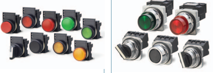
Pilot Devices
If control or pilot devices, for example push buttons, selector switches and indication lights, are required locally at the starter, they shall be installed and mounted on the draw-out starter pan. Requirements shall be specified on one line diagram.
Terminal Blocks and Wiring
Where MCC is wired-type B or C as defined in NEMA ICS 2, control terminal blocks shall be mounted at the front of the starter cubicles. Starter and motor control wiring shall be 2.5 mm2, 600 V stranded copper, with cross-linked polyethylene or thermoplastic insulation, rated at 90 qC or greater. Power wiring shall be sized to carry the maximum NEMA full load current of the unit.
Where control wiring will be terminated on terminal blocks, they shall be labeled, pull-apart type, with 20 percent spare terminal points provided. Control inter wiring within MCC shall be labeled accordingly.

Main keywords for this article are Motor Control Center Design Guide, Motor Control Center Layout, MCC Schematic Diagram, Motor Control Center Wiring Diagram, MCC Panel Components.


Spare Locations
A „spare‟ MCC shall be arranged for future expansion, and the enclosures shall be of modular design to permit safe and easy installation of additional units. These units shall include, but not be limited to, such items as pre drilled buses, terminal blocks for secondary wiring, and removable enclosure and covers secured by captive hardware on the structure. Enclosure for the future shall be completely equipped, with circuit breaker, control power transformers, bus bars, and wiring to make an operating MCC, as specified on the one line diagram.
Space Location
- Space locations shall be covered, empty cubicle locations. Space locations shall be sized to accommodate various starter sizes.
- Space location shall be identified with a nameplate fastened to the cubicle door. Nameplate shall match the unit nameplates and shall identify the location as a space.
- There shall be a minimum of one „spare‟ and „space‟ location connected to every bus for future expansion, as specified on the one line diagram.
Grounding
- Starter units shall be grounded in accordance with UL 845.
- MCC assembly shall be designed and constructed to ensure proper grounding of the individual units. Maximum resistance between the individual starter enclosures and MCC ground bus shall not exceed 0.005.
MCC Incoming Line Arrangement
Primary Terminations
- The primary incoming connection may be made by cable, bus connections or wire in conduit.
- Cable or Wire Terminations. If the primary connection will be made by cable or wire in conduit, the appropriate size and number per phase of crimp or compression type cable lugs shall be provided, based on the size and type of cable to be used. Cables up to 300 mm2 shall have NEMA two hole lugs. Cables larger than 300 mm2 shall have NEMA four hole lugs.
- Busduct Termination. If the primary connection will be made by busduct, the proper provisions for connection to a bar type busduct, rated as shown in SES E09-X01, shall be installed at the top of compartment.
Other Incoming Line Considerations
- Cable or conduit entrance can be from the top or bottom of any vertical section, and shall be discussed. Cable shall be pulled and connected from the front.
- The top of each vertical section shall be fitted with a bolted flat plate that can be removed to allow the drilling or punching of entrance holes for cables or conduits.
- Cables shall be routed directly to the incoming line lugs, the main breaker, the disconnects or terminals within the starter unit.
- No horizontal wireways shall be permitted in incoming line sections.
- No wiring shall pass through incoming line sections.
- Incoming power cable sizes shall be as indicated in data sheet.
- Incoming line metering shall be in accordance with one line diagram.
- Main keywords for this article are Motor Control Center Design Guide, Motor Control Center Layout, MCC Schematic Diagram, Motor Control Center Wiring Diagram, MCC Panel Components.
MCC Buses
- Phasing for buses and component terminals shall conform to NEMA standards for power switchgear assemblies.
- Standard bus shall be copper. Horizontal and vertical buses shall be tin or silver plated.
- Horizontal and vertical busing shall be braced to withstand the minimum RMS symmetrical fault current of 42 kA at a utilization voltage of 480 V, or as specified in data sheet.
- Bus ratings shall be based on 50°C rise over a 40°C ambient.
- Bus bar spacing and the spacing of bus fastening point shall not be less than specified in UL 845.
Horizontal Bus
- Each MCC section shall contain three main horizontal bus bars, housed in an isolated compartment, which shall run continuously through all sections of MCC, with provision made for extension at either end for future expansion.
- Bus bar and other types of bolted connections in the bus compartment shall be accessible from the front of MCC line up through sliding or removable covers in each vertical section.
- The main horizontal bus shall be continuous and unspliced within each shipping section. Where the buses are spliced for shipping purposes, the contact surfaces at the splice joint shall be tin or silver plated. The bolts, springs, washers, splice plates, and instructions required to complete the splice shall be provided.
- The main horizontal common power bus shall have a continuous current rating of 600, 800, 1000, 1200 Amperes or higher as required by a particular application, unless otherwise specified in data sheet.


Vertical Bus
- Each vertical section shall contain three full length copper vertical bus bars connected to the horizontal main bus bars at the top of each vertical section.
- The vertical buses shall be isolated from the starter unit area of the vertical sections by a barrier made of a rigid insulating material.
- If MCC will not be equipped with a shutter mechanism to close the plug-in stab openings to the vertical bus, plugs shall be provided in the unused plug-in stab openings.
- The vertical bus extensions installed in a section shall have a minimum continuous current rating of 300 Amperes unless otherwise specified in SES E09-X01.
Ground Bus
- A continuous, horizontal tin-plated copper ground bus shall be located across the complete length of MCC lineup, with provisions made for extensions at either end for future expansion. Provisions shall also be made to terminate a 120 mm2 copper ground system cable at each end. The ground bus shall be routed at the lower rear of the line up.
- Minimum current rating of the horizontal ground bus shall be 300 A.
- A vertical grounding bus shall be provided in each vertical section that makes contact with the plug-in units before the bus stabs engage the vertical bus.
Fault Current Capacity
An evaluation of the overall short circuit capacity of the system to which the MCC shall be installed shall be performed prior to the selection of components, to determine the required interrupting rating of the protective devices to be used, and the level of bus bracing required.
The minimum short circuit current rating shall be 42 kA RMS symmetrical amperes at a utilization voltage of 480 V. Each type of equipment installed in the MCC shall be suitably rated.
Note: Main keywords for this article are Motor Control Center Design Guide, Motor Control Center Layout, MCC Schematic Diagram, Motor Control Center Wiring Diagram, MCC Panel Components.
MCC Panel Components
MCC Starter Units
NEMA Standard Sizes
- Motor starters shall be built and sized in accordance with NEMA AB 1, ICS 1 and ICS 2, and controlled by microprocessor.
- Minimum motor starter size shall be NEMA Size 1.
- Combination motor starter units from Size 1 to Size 4 shall be drawout type, provided with self-aligning silver-plated plug-in stabs for connection to the vertical bus.
- The drawout unit shall be supported in the MCC section on guide rails and latched into place by a racking mechanism which allows the unit stabs to be locked in the connected or disconnected position.
- Each starter shall be provided with two normally opened and two normally closed auxiliary contacts, wired to the terminal block.
- Starter units Size 5 and larger shall be bolt-in units.
Circuit Breaker
- Circuit breakers for combination motor starters shall be adjustable magneticonly trip (MCP), three pole, molded case, and rated at 125 percent of the motor full load amperes (FLA).
- Minimum frame size for breakers shall be 100 A.
- Minimum short circuit interrupting rating shall be as in 7.5.2.
- Molded case breakers shall conform to UL 489 and NEMA AB 1.
- Feeder breakers shall be thermal magnetic.


Contactor
The motor starter contactor shall be a heavy duty magnetically operated air break type, rated for the maximum continuous current of the NEMA size starter it will be installed in.
Thermal Overload Relays
- Thermal overload protection shall be provided in each phase or ungrounded conductor, and shall be of the ambient temperature compensating type.
- The overload relays shall also provide phase failure and phase unbalance protection.
- Thermal overload devices used on motor circuits may be manual or automatic reset.
- Solid state overload relays like Motor Logic plus or approved equal are also acceptable.
Safety Interlocks
Each starter compartment door shall be interlocked mechanically so that it cannot be opened unless the unit disconnect operating handle is moved to „Off‟ position. However, the door-operating mechanisms shall be designed to allow a qualified person to release the door with a screwdriver for inspection, without interrupting power.
Control Power Transformer (CPT)
- Each starter shall be provided with a dedicated CPT.
- CPT shall be the manufacturer‟s standard continuous rating. Minimum size shall be 100 VA.
- Ungrounded CPT primary leads shall be fused in accordance with NEC Article 450-3(b).
- Ungrounded secondary leads shall be fused at the ampere rating of the CPT secondary.
MCC Monitoring and Control
- Control, protective relaying, metering and monitoring shall be the microprocessor based configurable controller.
- Microprocessor shall be capable of monitoring electrical current, receiving commands either by contact closures or digital data, giving commands by means of contact closure to the motor starters and other devices under its control, and transferring information by alphanumeric display to the operator and by digital signals to other equipment.
- Microprocessor unit shall be mounted on the door of the starter. Specific data entry to suit the actual application shall be programmed into the device in accordance with manufacturer‟s instructions.
- Unit shall draw its power from a CPT located in the starter unit of 120 V power supply.
- When specified on one line diagram, the following motor protection functions shall be required. Numbers in parenthesis are ANSI device numbers:
a. Overload (49/51)
b. Locked rotor (48)
c. Phase unbalance (46)
d. Ground fault (50G/51G)
e. Undercurrent/under power (37)
f. Overtemperature (49)
g. Under voltage (27)
h. Acceleration (18)
9.6 Monitoring and Metering
a. Voltage
b. Current (RMS of each phase)
c. Power
d. Energy
e. Percent unbalance
f. Thermal capacity used
g. Motor loading
h. Ground fault leakage current
- Remote Monitoring and Communications. RS 485 interface shall be provided to enable serial communication of monitored data to a remote computer.
MCC Special Requirements
The following components shall only be provided if specified in project based design and one line diagram.
Lighting Contactors
- It is used in applications where it is not critical that contacts remain closed if control power is lost
- AC contactors shall for the local or remote switching of general purpose lighting and heating loads of relatively large size.
- Contactors used for the switching of large lighting and heating loads shall be fully rated.
- We have Typical applications for Lighting contactors:
• Schools
• Hospitals
• Office buildings
• Industrial plants
• Hotels
• Shopping centers
• Airports
• Stadiums
• Resistive heaters


Adjustable Frequency Drives (AFD)
- Adjustable frequency drives can be installed in vertical sections as an integral part of the motor control center.
- AFD shall be used to control standard 460 V, 3 phase, 60 Hz, variable torque, NEMA B squirrel cage induction motors up to 150 kW.
- AFD shall be equipped for remote control of start/stop and speed control, through a communications link.
- Operator adjustable controls shall be mounted on the unit front panel and other non-adjustable controls shall be mounted within AFD vertical section. Any exceptions shall be stated.
- The type of equipment to be driven by AFD/motor shall be described on the single line diagram and in data sheet.
- AFD shall:
c. Include an auto restart feature, which shall allow a ride through capability due to momentary power losses of up to two seconds
d. Include the necessary components and circuits to protect AFD and motor from sustained motor overload, internal faults in AFD or motor, and disturbance in the incoming ac supply.
e. Be provided with internal self-diagnostic circuits to detect and identify failures - For conditions which shall cause shutdown (ac output voltage reduced to zero) of the AFD/motor.
- For AFD testing, inspection and data requirements, see Medium Voltage Variable Frequency Drives Design Requirements.
")
High Resistance Ground Detection System
- High resistance ground detection systems shall be included as an integral part of MCC.
- This equipment provides an immediate warning when a ground fault occurs, and provides a method for locating and removing the fault before another fault develops on another phase, thus preventing circuit outages due to double line to ground faults.
- The ground detection equipment shall match MCC in construction, finish, nameplates, wiring size and type.
- The ground resistor and ground detection equipment shall be provided, wired and tested.

Power Factor Correction Capacitors
Power factor correction capacitors conforming to Capacitors Selection for Power Factor Improvement can be mounted directly in MCC sections, if required. Requirements shall be shown on the single line diagram.
Motor Re-acceleration
Where “Auto Restart Circuitry” is required, control circuitry shall be provided to automatically restart the motor after an adjustable time delay following a momentary power interruption. The circuitry shall include a pneumatic timer (having an adjustable range of 0-10 sec.) to prevent the restart if the power outage lasts longer than a preselected time, and an electronic timer (having a range of 0-50 sec.) to allow for a sequence restarting of the motor once power returns. The timers shall be industrial type and shall have a repeat accuracy of ±5% or less. Detail shall be shown on single line diagram.
Automatic Transfer Switches (ATS)
Automatic Transfer Switch (ATS) is a high availability switch that provides redundant power to connected equipment and has two input power cords, one for each AC source. The Rack ATS supplies power to the connected load from a primary AC source. If that primary source becomes unavailable, the Rack ATS automatically transfers loads to the secondary source.
The most common application of automatic transfer switches is in the switching of critical load from a preferred utility source to an onsite engine driven generator power source.
- Automatic transfer switches can be installed as an integral part of the motor control center also.
- The ATS shall be electrically operated and mechanically held. Specific ATS ratings and configuration shall be part of the single line and data sheet.
- The ATS shall consist of an inherently double throw, positively locking, power transfer switch mechanism and a microprocessor-based controller to provide automatic operation.
- The switch shall be mechanically interlocked to ensure normal and emergency are the only possible positions.
- The electrical operator shall be single solenoid momentarily energized mechanism.
- Inspection of the condition of all contacts shall be possible from the front of the ATS unit without disassembly or de-energization.
- All components of the ATS shall be rated for continuous duty. Where circuits with neutral conductors are being switched, a fully rated overlapping neutral transfer contact shall be provided.
- Momentary-contact three-position test switch shall be provided for test/automatic/reset modes.
- Two normally open and two normally closed 10 amp dry contacts shall be provided for engine start up/cool down sequence.
- Auxiliary 10 amp dry contacts shall be provided for “switch in normal” and “switch in emergency” status or control.
- Indicating lights shall be provided for both switch position and power source availability.
- Controller logic shall provide option of not transferring to emergency source if normal source has been restored.
- Controls for off-line engine exercising shall be provided.
- Controller shall be equipped with internal self-diagnostic circuits to detect and identify failures.
- Controller shall be equipped with an RS 485 interface to enable serial communication of monitored data to remote facility computers.
- The ATS shall be function tested at the factory along with all other major components of the MCC to insure compliance with all requirements stated on the data sheets.
- The following operational parameters shall be adjustable for the ATS:
(i) Nominal line voltage and frequency
(ii) Single or three phase sensing - The following parameter shall be continuously monitored for both the normal and emergency sources:
(i) Undervoltage
(ii) Overvoltage
(iii) Underfrequency
(iv) Overfrequency
(v) Voltage unbalance
(vi) Phase rotation – source shall not be accepted if not matching the selected rotation
")
Note: Main keywords for this article are Motor Control Center Design Guide, Motor Control Center Layout, MCC Schematic Diagram, Motor Control Center Wiring Diagram, MCC Panel Components.
")
Time delays
The controller shall provide time delays for the following functions:
(i) Override momentary outages of normal source
(ii) Transfer to emergency
(iii) Re-transfer to normal
(iv) Re-transfer to normal, test mode
(v) On shutdown for engine/general cool down
The controller shall provide one time delay output that may be used for any of the following:
(i) Normal to emergency
(ii) Emergency to normal
(iii) Prior to transfer
(iv) Prior to and after transfer
(v) Normal to emergency and emergency to normal
(vi) All transfer conditions
(vi) When both sources are available
MCC Testing and Inspection
MCC shall be tested for the following in accordance with UL 845.
a. Visual inspection of construction, workmanship, dimensions and internal wiring
b. Relay and metering circuits shall be energized and devices checked, to ensure that polarities are correct, elements are in operating condition, and relays are performing the desired function
c. No-load operational tests of contactor shall be performed at maximum, standard, and minimum control voltage ratings
d. Operation of mechanical interlocks
e. Short circuit tests
f. Dielectric voltage withstand test
g. Size and rating of each type of equipment, compared to the requirements of the purchase order
h. Factory setting of contact gap
i. Insulation resistance test
Note: Main keywords for this article are Motor Control Center Design Guide, Motor Control Center Layout, MCC Schematic Diagram, Motor Control Center Wiring Diagram, MCC Panel Components.