This article is related to electrical installation with pictures explained. Main keywords for this article are MOTOR INSTALLATION DETAILS ABOVE GROUND, MOTOR INSTALLATION DETAILS BELOW GROUND, MOTOR TERMINATION ASSEMBLY.
MOTOR INSTALLATION DETAILS ABOVE GROUND
- Low Voltage Separate Power and Control-Steel wire Armor cable


- Medium Voltage Separate Power and Control – Steel wire Armor cable


AO1B – 5kV POWER CONDUCTOR AS SPECIFIED IN CABLE SCHEDULE. FOR SUPPLEMENTAL GROUNDING OF MOTOR WITH CONTROL
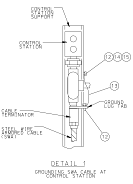
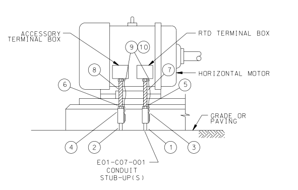
NOTE: STATION SUPPORT REFER E01-C03-011.

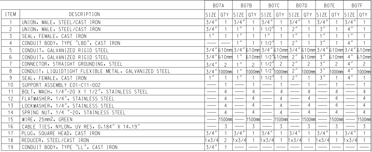
- Low Voltage Motor Accessory Box Connection Combined With Control wires -Steel Conduit

NOTES: FOR SUPPLEMENTAL GROUNDING OF MOTOR WITH CONTROL STATION SUPPORT. REFER DWG. E01-C03-011
- Low Voltage Power Only -Steel Wire Armor Cable

600V POWER CONDUCTORS AS SPECIFIED IN CABLE SCHEDULE.
- MV Power Only – Steel Wire Armor Cable

5KV POWER CONDUCTOR AS SPECIFIED IN CABLE SCHEDULE
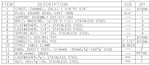
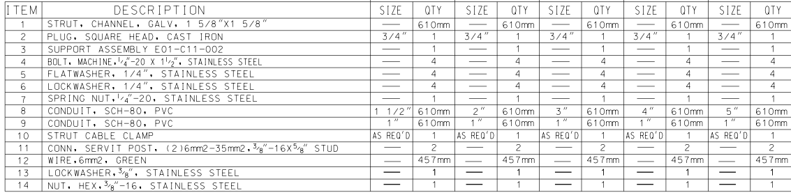
- Motor Termination Assembly 480V Motors and Below

- MOTOR TERMINATION ASSEMBLY 480V MOTORS AND BELOW FOR CONDUIT CONNECTION

- MOTOR TERMINATION ASSEMBLY 460V MOTORS AND BELOW FOR SWA CONNECTION
NOTES:
1. INSTALLATION INSTRUCTIONS:
A. FOLLOW MANUFACTURERS INSTRUCTIONS WHEN FURNISHED WITH MOTOR CONNECTION KIT.
B. ALL MECHANICAL CONNECTIONS TO BE CLEAN AND TIGHT.
C. REMOVE ALL SHARP EDGES FROM CONNECTIONS BEFORE INSTALLING TUBING.
D. INSTALL HEAT SHRINKABLE TUBING AROUND LUGS AND HEAT AS INSTRUCTED.
2. GROUND WIRE, SIZED PER NEC TABLE 250-122, TO MOTOR BASE GROUND AND/OR OTHER GROUND LUG TABS, SEE E01-C03-011.
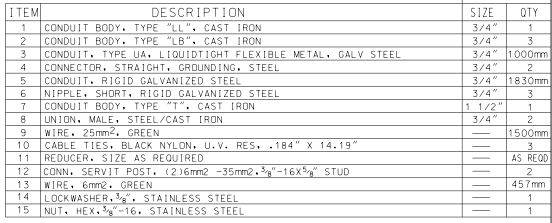
- Motor Termination Assembly 5KVMotors and Above

NOTES:
1. INSTALLATION INSTRUCTIONS:
A. FOLLOW MANUFACTURER’S INSTRUCTIONS WHEN FURNISHED WITH MOTOR CONNECTION KIT.
B. ALL MECHANICAL CONNECTIONS TO BE CLEAN AND TIGHT.
C. REMOVE ALL SHARP EDGES FROM CONNECTIONS BEFORE INSTALLING TUBING.
D. INSTALL HEAT SHRINKABLE TUBING AROUND LUGS AND HEAT.
2. GROUND WIRE, SIZED PER NEC TABLE 250-122, TO MOTOR BASE GROUND AND/OR OTHER GROUND LUG TABS, SEE E01-C03-011.
8. Control Station Support Location Plan,

Above Ground Feed
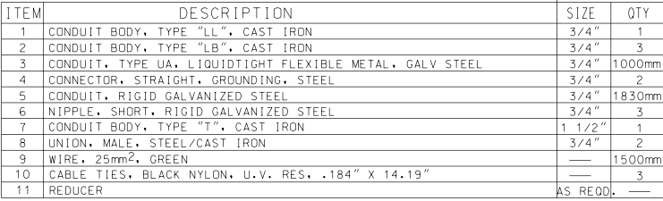
- RTD and Accessory Terminal Box Connections For 5KV Motors-Steel Wire Armor Cable

10. Combined Power And Control-Steel Conduit

MOTOR INSTALLATION DETAILS BELOW GROUND
- Low Voltage Separate Power and Control-Steel wire Armor cable


- Medium Voltage Separate Power and Control -Steel wire Armor cable

- Motor Accessory Box Connection Combined with Control Wires -Steel Wire Armor Cable

- Power Only-Steel Wire Armor Cable

- Control Station Support Location Plan, Belowground Feed


NOTES:
1. ALL MOTOR DATA LISTED ABOVE IS BASED ON 460 VOLT, 1800-3600 RPM T.E.F.C. MOTOR ENCLOSURES WITH CAST IRON TERMINAL BOXES.
2. FIELD TO POSITION MOTOR MOUNTING HOLES ON VERTICAL PUMP ASSEMBLIES SO THAT CONDUIT BOX IS LOCATED AS SHOWN.
3. MOTOR TERMINAL BOXES ARE TO BE ROTATED SO AS TO ALLOW FOR CONDUIT ENTRY FROM THE LEFT SIDE FACING BOX.
4. PRIOR TO PLACING CONTROL STATION SUPPORT ASSEMBLY IN PLACE, FIELD IS TO VERIFY DIMENSIONS FOR ACCESSIBILITY AND CLEARANCE.
5. ADJUST GIVEN DIMENSIONS IN INCREMENTS OF 50mm WHERE PUMP FOUNDATION CONFLICTS WITH DIMENSIONS IN TABLE.
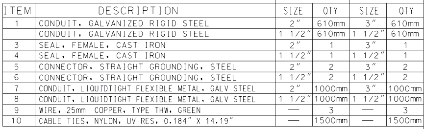
RTD and Accessory Terminal Box Connections For 5KV Motors-Steel with Armor Cable


- Separate Power & Control-Steel Wire Armor Cable -5KV Motors

Separate Power and Control-Steel Conduit

- Motor Accessory Box Connection Combined with Control Wires -Steel Conduit

- Power Only-Steel Conduit


- RTD and Accessory Terminal Box Connections – For 5KV Motors-Steel Conduit
- Separate Power and Control-Steel Conduit – 5KV Motors


Like!! Great article post.Really thank you! Really Cool.