This article establishes the minimum requirements for the mechanical design, materials, fabrication, and size of orifice plates. Main keywords for this article are Orifice Plates Design Requirements. Orifice Plate Basic Design. Orifice Plate Application. Orifice Plate Advantages. Orifice Plate Disadvantages.
Orifice Plate References
Reference is made in this article to the following documents.
American Petroleum Institute (API)
- RP 550/551 Installation of Refinery Instruments and Control Systems
International Organization for Standardization (ISO)
- 5024 Petroleum Liquids and Gases – Measurement – Standard Reference Conditions
- 5167 Measurement of Fluid by means of Pressure Differential Devices
- 5168 Measurement of Fluid – Estimation of Uncertainty of a Flow-rate Measurement
Orifice Plate Definitions
For the purpose of understanding this standard, the following definitions apply.
Beta Ratio. The ratio of the diameter of the constriction to the pipe diameter, B = D const / D pipe.
Corner Taps.
The differential pressure signal location in an orifice flange union defined by the corner formed between the orifice plate and the internal diameter of the flange.
Flange Taps.
The 1 / 2 inch or 3 / 4 inch pipe taps in the edge of an orifice flange union.
Header.
A conduit or chamber that receives fluid flow from a series of smaller conduits connected to it, or that distributes fluid flow among a series of smaller conduits.
Impulse Line.
Piping or tubing connecting the process to the sensor.
Kinetic Energy.
The energy of a working fluid caused by its motion.
Orifice Plate.
A disc or platelike member, with a sharp-edged hole in it, used in a pipe to measure flow or to reduce static pressure.
Orifice Run.
The differential pressure producing arrangement consisting of selected pipe, orifice flange union and orifice plate. An orifice run has rigid specifications defined by the American Gas Association.
Potential Energy.
Energy related to the position or height above a place to which fluid could possibly flow or a solid could fall or flow.
Primary Flow Element.
Any device placed in a flow line to produce a signal for flow rate measurement.
Pulsating Flow.
Irregular or repeating variations in fluid flow, often due to pressure variations in reciprocating pumps or compressors in the system.
Reynolds Number.
A dimensionless criterion of the nature of flow in pipes. It is proportional to the ratio of dynamic forces to viscous forces: the product of diameter, velocity and density, divided by absolute viscosity.
Vena Contracta.
The location where cross sectional area of the flowstream is at its minimum. The vena contracta normally occurs just downstream of the actual physical restriction in a control valve.
Orifice Plates Design Requirements in Process Industry
- Orifice plate technology is one of the most accepted, versatile, and simple methods of measuring flow. Applications are extremely broad, generally describing all flow measurements except those under extreme conditions of high viscosity, low static pressure or poor physical condition of the fluid, for example containing solids, dirt, heavy slurries and sewage.
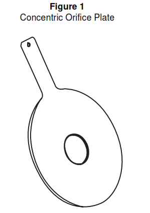
- Orifice plates are constructed in different types, concentric, conical, eccentric, integral, quadrant, and segmental. Concentric orifice plate is the most commonly used type, see Figure 1.
- An orifice is a differential pressure (head) producing primary flow element for use with indicating, transmitting, totalizing, or combinations of secondary instruments accepting differential pressure input. A measure of the differential pressure created across the orifice plate is a measure of flow rate.
- With sufficient information for orifice sizing, it is possible to design installations with errors of 1/2 to 1 percent of full scale depending upon Beta ratios and Reynolds numbers. This accuracy is required of flow measurement used for accounting purposes (material balance, buying, or selling). Installations normally provide errors of 1 to 4 percent. Common errors of flow measurement result from improper tap location, round edges (sharp-edged orifice), viscosity variation, inside pipe diameter differences, and impulse line head difference.
- Accuracy is highly dependent upon correct fabrication and installation of the orifice plate and the associated piping.
- The sum of static energy, kinetic energy, and the potential energy of the fluid is approximately consumed in the flow across a pipe.
- The velocity of the fluid increases when the cross sectional area of the pipe is reduced.
Orifice Plate Basic Design
- Orifice flow measurement is derived from Bernoulli’s Theorem and is given in the simplified equation:
Q = kA √h/e Where
Q = Volume flow rate
A = Cross-sectional area of the pipe
h = Differential pressure between taps
e = Density of the flowing fluid
k = Constant which includes the ratio of pipe diameter to orifice diameter (Beta ratio) and correction factors - The basis of manufacture shall be in accordance with the latest ISO and ANSI data, using the ISO 5167 sizing equation, the ISO 5168 accuracy standard, and ISO 5024 volumetric standards.
- Sizing calculation shall use base conditions of 15°C and 101.325 kPa. Flow values to be used shall be integers.
- The orifice plate Beta ratio shall be between 0.20 and 0.60 for liquids and between 0.20 and 0.70 for gases and steam. Beta ratio of 0.75 is acceptable for orifice plates in 24 inches and larger pipelines.
- Orifices for liquids are usually sized for full-scale reading at a differential pressure of 2500 mm WC. This allows an increase or decrease in the meter range for different flow rates without changing the plate. For gas or steam flow, a general rule is that the meter range, in inches of water, should not exceed the flowing pressure, expressed in pounds per square inch absolute
- Orifice plate material shall be 316 SS. Other material compatible to process fluid shall be used where 316 SS is not suitable.
- Orifice plate thickness shall be between 0.005 D and 0.02 D.
- For Beta ratios outside the 0.2 to 0.75 range, the sharp edge thickness of an orifice plate shall not exceed the smallest of:
a. d/8 where d = orifice plate bore.
b. D/50 where D = inside pipe diameter.
c. D-d/8. - Orifice plate thickness for raised face flanges shall be:
a. 50 mm to 300 mm = 3.175 mm.
b. 350 mm to 600 mm = 6.35 mm. - Orifice flanges shall have a minimum ANSI Class 300 rating.
- To avoid errors resulting from disturbances of the flow pattern due to, for example, valves and fittings, a straight run of smooth pipe before and after the orifice is recommended. Required length depends upon the Beta ratio and the severity of the flow disturbance and upstream and downstream straight pipe length shall conform to ISO 5167.
- Straightening vanes may be required in the pipe upstream of the orifice.
- Drain holes shall be provided in steam and gas flow service when condensation possibility exists. Vent holes shall be provided for liquid service where a potential for gas entrainment exists.
- Pressure taps shall be located in the flange for small pipes. Taps shall be located on the pipe for large pipes.
- Tap size shall be 0.5 inch NPT (F).
- Differential pressure taps are distinguished by the spacing between the orifice plate and the pressure tap. The upstream distance is called K1, the downstream K2.
- Flange taps are the most commonly used. These taps are located 1 inch upstream and 1 inch downstream, and are drilled through the flanges which hold the orifice plate. A minimum of Class 300 flange thickness is required to accommodate the pressure-tap drilling.
- Flange taps shall be located on the flange 1 inch upstream and downstream faces of the orifice plate. Flange taps shall be used for pipe sizes 2” to 16”. For sizes greater than 16” D, D/2 taps shall be used. Corner taps shall be used for sizes 1 inch and smaller.
- Taps for liquid service shall be located on the side or bottom of the pipe. Taps for gas service shall be located on the top.
- Orifice plates shall be furnished with handles or tabs which are of sufficient width to pass between two adjacent bolts and extend beyond the outside edge of the orifice flanges.
- The following information shall be stamped on the upstream side of the handle of all orifice plates:
a. tag no.
b. upstream.
c. orifice bore.
d. inside diameter of pipe.
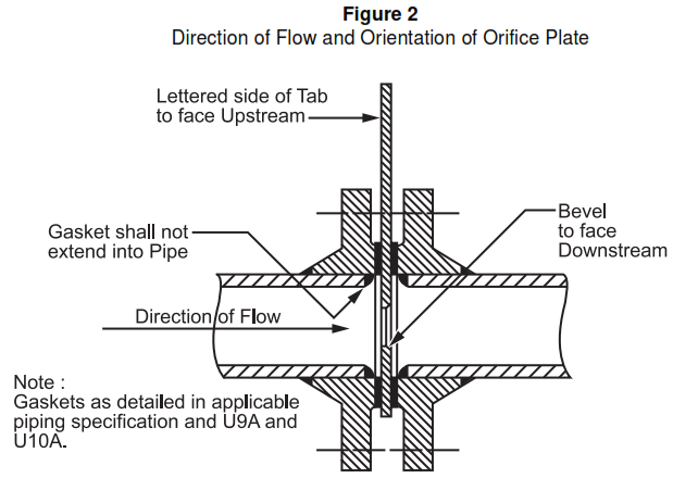
e. material. - Installation of instruments shall conform to API 550/551. See Figure 2 for details.
Orifice Plate Application
- ISA standard sharp-edged, concentric orifice plates shall be used in all installations that indicate, record, and transmit process flow measurements unless process conditions require otherwise. If unrecoverable pressure loss or other constraints preclude their use, another measuring device shall be selected. They may be used across wide ranges of Reynolds numbers. If the orifice is designed for a Reynolds number not less than 100,000, the calculated coefficients are likely to have a tolerance of less than one percent, unless other limits are violated. This tolerance increases to more than two percent with smaller Reynolds numbers. The recommended minimum Reynolds number for a given application may range from 10,000 to 25,000.
- Segmental and eccentric orifice plates should be used for fluids containing suspended solids. Calibrated orific runs should be purchased for high accuracy accounting installation.
- Because of the unpredictable nature of the vena contracta, accurate flow measurement of compressible fluids in the supercritical range (differential pressure is greater that 55 percent of the upstream absolute pressure) should not be attempted.
- The direction of flow in vertical lines is a subject of considerable controversy. Tests have shown that concentric orifices in vertical pipe runs are satisfactory for liquid with entrained gases for either upward or downward flow. If a downward flow is to be selected, special care is required to ensure that the pipe, including the recommended straight section upstream of the orifice, is maintained full of the flowing fluid. The flow direction of the stream or gas in a vertical pipe may be either upward or downward if the impulse line head differences are equalized.
- Standard calculation procedures generally are inadequate for installations in pipelines below 1 1/2 inches. Vendor designed and fabricated orifice flow runs should be considered in these cases. These runs include the orifice and upstream and downstream sections calibrated as a unit.
- Several manufacturers offer special packages of small orifice plates and differential pressure transmitters for low flows of 5 gpm and below. Some of these packages locate the orifice within the transmitter and the name ‘integral orifice’ is often used. Current designs tend towards using a miniature orifice run to gain the advantages of using standard manifolds and separating the transmitter from process temperatures. Orifices may use special materials, for example sapphire in the smallest (0.002 in) sizes. Flow fluctuations of ± 3 to 5 percent are quoted for uncalibrated transmitters, with considerable improvement when they are calibrated. Note that flow calibration of a small meter may be relatively inexpensive depending upon requirements. With the small dimensions involved, it is necessary to check the Reynolds number over the flow range of interest to avoid significant departure from the expected flow-squared relation expected for orifice meters. Check with the manufacturers for details of material availability and temperature and pressure limitations.
Orifice Plate Installation
- Sharp-edged orifice plates with a beveled edge shall be installed with the bevel facing downstream.
- Quadrant-edged orifice plates are installed with the rounded edge upstream. Beveled orifice plates installed backwards can have errors exceeding 30 percent with the flow being higher than calculated.
Orifice Plate Operation
- Pulsating flow from reciprocating pumps and compressors will significantly affect the differential pressure developed by a head-type meter if the pulsation remains at a high amplitude when it reaches the primary device. Orifice plates should not be used if high accuracy is required. It has been reported by the joint ASME-AGA Committee on Pulsation Research that for pulsation amplitudes of 24, 48, and 96 percent, corresponding errors of plus or minus 1, plus or minus 4, and plus or minus 16 percent can be expected. Damping of the flow pulsations will reduce errors. Damping of the pressure tap leads (impulse lines) will not result in significant improvement due to the small volumes of the leads.
- Measurement may be improved by one or a combination of the following:
a. operating at a higher differential (that is, shutting off one or more runs in a multiple meter run installation).
b. installing a higher range differential instrument and changing operating conditions, to use the increased range with the existing orifice, for example by reducing the flow pressure.
c. reducing the pipe run diameter to use a higher orifice-to-pipe diameter ratio, still operating at differentials as high as practicable. Increasing the Beta ratio will reduce the pulsation error if the operating differential remains constant.
d. installing mufflers, headers, restrictions, or combinations of capacity and pressure drop between the primary device and the source of the pulsation to reduce pulsation amplitude.
e. locating the primary device at a point where the pulsation amplitude is lower, for example on the suction side of compressors. - Where maximum accuracy is important, it is recommended that the maximum-to-minimum flow ratio should not exceed 3:1. Where flow variations approach 10:1, two differential pressure sensors with consecutive ranges are recommended.
- The orifice plate shall be inspected periodically for wear of the bore and the sharp edge.
Orifice Plate Advantages
- Orifice plates are easily installed between flanges.
- Fabrication is relatively simple and inexpensive.
- Almost any chemically active or corrosive fluid can be metered due to little or no limitations on the materials of construction.
- Easily fabricated and duplicated on the plant.
- Orifice characteristics are well known and predictable.
- Orifice plates can accommodate a wide range of pipeline sizes and flow rates.
- Capacity can be increased by reboring the original plate or recalibrating the transmitter.
Orifice Plate Disadvantages
- Impractical for systems with low static pressure.
- Flow rate is proportional to the square root of the pressure drop, so the calibration curve is quadratic, limiting measuring range to about 3:1 with the older 0.5 percent differential pressure transmitters. Newer 0.1 percent accuracy transmitters can increase this to 5:1. Note also the Reynolds number accuracy. This is a function of the differential pressure measuring device and is based upon the fact that at one-third of flow, the pressure difference is approximately one-ninth of that at maximum flow. Accuracy can be retained by using a better differential pressure sensor or by adding a second differential pressure sensor calibrated for a lower differential, then switching signals to maintain accuracy.
- Straight runs of pipe are required upstream and downstream of the orifice plate.
- Sharp-edged orifices are inaccurate at low Reynolds numbers.
- Differential pressure varies as the square of the flow rate, so the pressure drop increases rapidly as the flow rate increases.
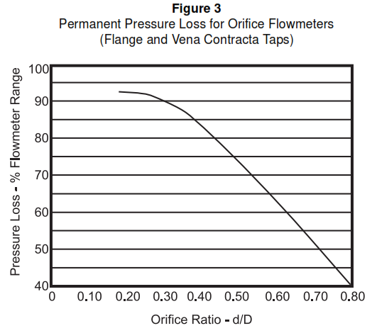
- High permanent pressure loss. See Figure 3.
- Subject to inaccuracies as the sharp, upstream edge of the orifice plate wears.
- Accuracies decrease with Beta ratios above approximately 0.7.
- Subject to damage by water hammer and foreign objects.
Main keywords for this article are Orifice Plates Design Requirements. Orifice Plate Basic Design. Orifice Plate Application. Orifice Plate Advantages. Orifice Plate Disadvantages.


