This article is about ”OVER SPEED PROTECTION IN COMPRESSOR CONTROL SYSTEM” and focusing to the engineers, technicians and supervisors. You will find lot of documents related to this article. Just navigate our website www.paktechpoint.com and find more articles. Please! Do not forget to subscribe our You tube channel also. Thanks in Advance.
OVER SPEED PROTECTION IN COMPRESSOR CONTROL SYSTEM
The over speed protection (OSP) system is completely isolated from the control system and is used to protect the system against over speed. The Over speed protection system is installed in the same cabinets in which the control system is installed.
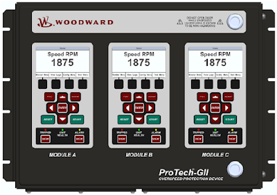
The ProTech-GII is a device designed to safely shutdown steam, gas and hydro turbines, as well as motors, compressors, reciprocating engines and other equipment, upon sensing an over speed or over-acceleration event.
The ProTech-GII consists of three independent modules whose trip outputs are either independent or voted in a 2-out-of-3 configuration. The ProTech-GII includes Overspeed/Over-acceleration, Alarm, and Trip log functions with time stamping. Indication that a test was active at the time of the event is provided on all logs and first-out indications are provided for Trip logs.
POWER SUPPLY
The compressor control systems will be based on a uniform design and layout. Depending of the exact I/O requirements for each of the individual units, the amount of I/O may vary. Consequently the power supply requirements for each system may be slightly different.
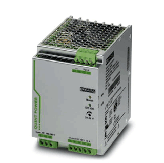
The CCS system shall be fed from a redundant UPS with 120VAC. The UPS supply feeds the MicroNet Plus, the ProTech GII, cabinet fans and 2 switch-mode AC/DC power supplies converting the input power to 24VDC. Each 120VAC consumer has a separate breaker.
A summing diode combines the 2 24VDC outputs into a single redundant 24VDC supply. The 24VDC supplies network switches, and various I/O related consumers. Each 24VDC consumer has a separated fuse.
The MicroNet chassis is supplied with 120VAC through its 2 power modules. The chassis power modules supply all chassis modules including CPUs and I/Os.
Please read also:
SOFTWARE TOOLS IN COMPRESSOR CONTROL SYSTEM
Fundamentals of Process Control and Automation? Explain with Examples of control system?
Anti-Surge Control Theory and Quench Control Theory of Compressor
MEASUREMENT SYSTEMS IN AUTOMATION AND PROCESS CONTROL SYSTEM
COMPLETE OVERVIEW OF PROGRAMMABLE LOGIC CONTROLLER PLC
Overview of Compressor Control Functional Block diagram
COMPRESSOR MAP OF COMPRESSOR CONTROL SYSTEM

