This article is about Fundamentals of Process Control and Automation and focusing to the engineers, technicians and supervisors. You will find lot of documents related to this article. Just navigate our website www.paktechpoint.com and find more articles. Please! Do not forget to subscribe our You tube channel also. Thanks in Advance. PLEASE SUBSCRIBE OUR PAKTECHPOINT YOUTUBE CHANNEL.
Fundamentals of Process Control & Automation
Feed Back Control System and Block Diagram

Feedback Control System
It is a control system that tends to maintain a prescribed relationship of one system variable to another by comparing functions of these variables and using the difference as a means of control.
Feedback Control System Elements
Sensor – a transducer* which converts the state of the controlled quantity to an electrical signal.
Selector (control input) – selects the desired state of the output.Usually it is a variable resistor.
Control Circuit – compares the desired state (control input) with the actual state (sensor) of the controlled quantity and sends an appropriate signal to the output transducer.
Transducer: A device that converts control signals from one form into other form. Most transducers have an output signal in the form of electrical energy.
Output Transducer – converts the electrical signal to the controlled quantity.
Controlled Quantity – usually not an electrical quantity, e.g. motor speed.
Feedback Path – usually not electrical, the Sensor detects the state of the controlled quantity.
Position Control feedback System – Servomechanism
A servomechanism is a power amplifying feedback control system in which the controlled variable is mechanical position.
It also implies to those systems which control time derivatives of position e.g. velocity and acceleration.
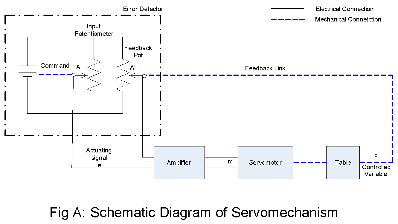 |
| schematic diagram of servomechanism |
Consider that the system of Fig A is to be used to control the angular position of a table in accordance with command signal originating from a remotely located station.
Steps in Obtaining Block Diagram
The steps in obtaining the block diagram is to identify
- the error-detector portion
- the control element
- the controlled system
- Error Detector Portion* – this requires merely finding the input and feedback transducers and the summing point of their output signal.
- For the system of Fig A above the error detector consists of the section blocked off with the dash-dot line.
- The Control Element – consists of the amplifier unit and the output motor.
- The table**, the position of which is being controlled, represents the controlled system.
When two signals of input and feedback transducers are compared , the result is the actuating signal. This portion of the system is identified as error-detector.
**In a specific application it may be a gun mount or the support table for a lathe or milling machine.
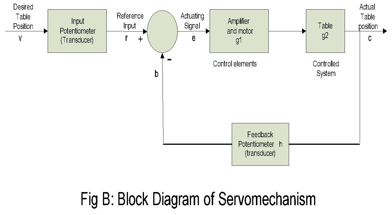 |
| block diagram of servomechanism |
Operation of the Servomechanism System
-
Assume that initially the slider arms of the input and feedback potentiometers are both set
- For this condition, the actuating signal (e) is zero, and so the motor has zero output torque.
- Next consider that the command calls for a new position of the table, namely, that corresponding to a
potentiometer voltage of +60mV.
- When arm A is placed at +60mV remains instantaneously at +50mV of the table inertia.
- This situation creates a +10mV actuating signal, which is really a measure of the lack of correspondence between the actual table position and the commanded position.
- A +10mV input to the amplifier applies input to the servomotor, which in turn generates an output torque, which in turn repositions the table.
- With negative feedback present the table moves in a direction which causes the potential of A’ to increase beyond +50mV. As this takes place, the actuating signal gets smaller and finally reaches zero, at which A’ has the same potential as A.
- The actual table position is therefore equal to the commanded value.
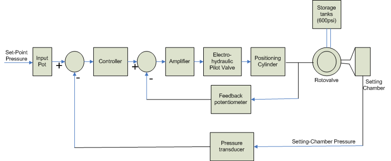
Supersonic Wind-Tunnel Pressure Control System

Information System Components
-
Pressure Transducer: A Pressure Transducer changes a pressure drop/rise into a corresponding
-
Amplifier: an amplifier is any device that converts one signal (often with a very small amount
of energy, a few milliwatt) into a another signal (often with a larger amount of energy e.g. several hundred watts).
- Feedback Potentiometer: A the amount of current that flows device that controls through a circuit.
- Electro hydraulic Pilot Valve: it is an electrically operated two-stage hydraulic amplifier. It consists of a coil agnet motor (which receives the electrical output of the preceding amplifier), a low pressure pilot valve and a high pressure pilot valve. The output motion of the latter drives the positioning cylinder which in turns the positions the rotovalve.
Operation of the System
-
Assume that a wind-tunnel test is to be performed at Mach* 5, to which the settling chamber pressure
-
An actuating signal immediately appears at the controller, which in turn causes the electro hydraulic
- As the rotovalve is opened, the input valve amplifier decreases because of feedback voltage to the pilot-the position.
- Moreover, as pressure builds up, the actuating signal to the controller decreases.
- When the settling chamber pressure has reached the commanded 250psia, the actuating signal will be zero and no further movement of the rotovalve plug takes place.
- The time needed to accomplish this is relatively small (about 5 s), and the attendant decrease in tank pressure is also very small.Consequently, an air flow of Mach 5 is established in the settling chamber.
Home Temperature Control System
Home Heating Temperature Control System
In home temperature control system we can take thermistor as example which measures temperature and sends signal to controller in modern digital system.
Please read also: TRANSFER FUNCTIONS OF CONTROL SYSTEM