This article is about MEASUREMENT SYSTEMS IN AUTOMATION and focusing to the engineers, technicians and supervisors. You will find lot of documents related to this article. Just navigate our website www.paktechpoint.com and find more articles. Please! Do not forget to subscribe our You tube channel also. Thanks in Advance. PLEASE SUBSCRIBE OUR PAKTECHPOINT YOUTUBE CHANNEL
MEASUREMENT SYSTEMS IN AUTOMATION AND PROCESS CONTROL SYSTEM
Measurement System
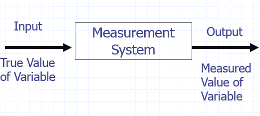
Measurement is the operation of determining the value of a quantity. A measurement or instrumentation system is the means used to carry out a measurement. The purpose of measurement system is to give the user a numerical value corresponding to the variable being measurement. We thus consider a measurement system to be a system which has an input of the true value of the variable being measured and an output of the measured value of that variable.
Functional Elements of Measurement System
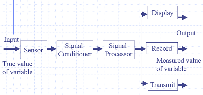
A measurement system can be considered to consist of several elements, each of which is used to carry out a particular function. These functional elements are:
Sensor:
This is the Element of the system which is effectively in contact with the proces for which a variable is being measured and gives an output which depends in some way on the value of the variable. Sensors take information about the variable being measured and change it into a form which enables the rest of the measurement system to give a value to it, e. g. a thermocouple is a sensor which has an input of temperature and an output of a small e.m.f.
Signal Conditioner:
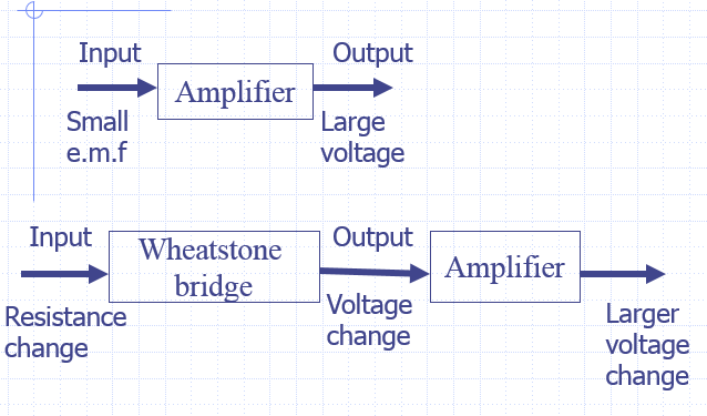
The signal conditioner puts the output from the sensor into a suitable condition for processing so that it can be displayed or handled by a control system. In the case of the thermocouple the signal conditioner may be an amplifier to make the e.m.f. big enough, with processing then being used to transform the voltage into a temperature reading on a meter as shown in the next slide figure.
Examples of signal conditioners are Wheatstone bridges which convert resistance changes into voltage changes. Amplifiers which are used to make signals bigger, and oscillators which convert an impedance change into a Variable frequency.
Signal Processor:
The signal processor processes the signal so that it is suitable for display or onward transmission in some control system. Example off signal processing elements are analogue to digital converts which put analogue signals into digital ones or perhaps handling by a computer, and filters which eliminate noise from a signal.
Please read also: Instrumentation Level Measurement with Calculation Examples
Data Presentation:
This presents the measured value in a form which enables an observer to recognize it. This may be via a display, e.g. a pointer moving across the scale of a meter or perhaps information on a visual display unit (VDU). The signal may be recorded, e.g. on the paper of a chart recorder or perhaps on magnetic disc. The output from signal processing may be transmitted into other elements in a control system so that it can be compared with a required value and action initiated to control the variable.
Weight Measurement System
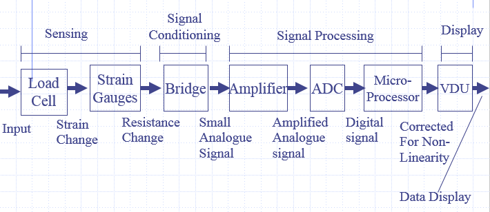
Broken down a measuremct1t system into its functional elements, consider a load cell that is used to determine the weight of a container The load cell is a cylinder on which strain gauges are mounted, the weight that is being measured compressing the cylinder and so changing the resistance of the strain gauges. The strain gauges are connected into a Wheatstone bridge and so the resistance change is transformed into a voltage change, the out-of-balance voltage of the bridge.
This voltage will be small, a few millivolts, and so it is amplified. Since the output is to be displayed on a visual display unit screen, the amplified voltage is converted into a digital signal by an analogue-to-digital converter.
Temperature Measurement System
Consider a thermocouple used for the measurement of temperature, the sensor is the thermocouple. The output from the thermocouple is conditioned by a circuit to give compensation for the cold junction not being at 00 C and an amplifier to make the signal bigger. The signal is then transmitted to a 0 to I0 V meter for display.
Information transporting systems
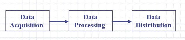
Measurement system can also be regarded as information transporting system. As information is taken about some variable, processing it and then distributing it to where it is required and in the form required. The system consists of three basic elements, namely:
1. Data acquisition
2. Data processing
3. Data distribution
Data Acquisition
Information is acquired from the object about some variable and converted into data. This involves the sensor and signal conditioning.
Data Processing
This is concerned with processing the signal carrying the data into a suitable form and condition to make the information available. This could involve filtering to reduce noise, amplification to make the signal bigger, combining signal from more than one sensor, etc.
Data Distribution
This involves the distribution of the information to where it is required. This can involve display, recording and/or transmission.
Quality Parameters of an Instrumentation system
The application for which it can be use Conditions required
Accuracy
Resolution
Sensitivity
Stability and Drift
Repeatability
Precision
Performance Parameters of Sensors/Transducers
The application for which it can be use This specifics The quantity for which the system can be used to obtain values and the range over which measurements can be made.
Range & Span: “Limits b/w input.”
It is the limits between which measurements can be made. For example, an instrument may be specified as a digital temperature measurement system with a range of 0 to +150oC. Or e.g. 0-50 kN
span=Max i/p-Min i/p ◊ 50 KN Range= 0 to 50 KN
Dead Band
The term dead band is used if there is a range of input values for which there is no output. For example. Bearing friction in a now meter using a rotor might result in no output until a particular flow rate threshold has been reached.
“Range of input values for which there is no o/p.”
Conditions Required
This might be a specification of power requirements and environmental conditions under which it can be used. Thus it might be specified as requiring a power supply of 110 V or 240 V. the selection to be by the setting of an internal switch, and to be operated when the relative humidity is less than 90%. Some might specify a temperature range within which the system can be used.
Accuracy:
The accuracy of a system is the extent to which the reading it gives might be wrong. For example, a thermometer might have an accuracy specified as ±0.1oC. This means that if the value given by the instrument is, say, 45.5oC, the actual temperature is between 45.4 and 45.6oC.
Accuracy is often specified as a percentage of the full range output or full-scale deflection. Accuracy may be affected by temperature, target reflectance or ambient light.
Error: “Diff b/w Measured & True Value.”
Error=Measured Value – True Value, e.g. if actual temp is 24oC & Measurement sys gives 250C, error is +1oC. It may be +ve or –ve.
Resolution:
“is the smallest change in distance that a sensor can detect, and is typically a smaller value than the accuracy error.” or “If there is the smallest change in i/p value & produces an observable change in the o/p.” For example a digital voltmeter might have a four-digit decimal display with a fixed decimal point, so that the maximum reading that can be obtained is 999.9. The resolution is thus 0.1, since no change smaller than this can change the reading given by the instrument.
Repeatability:
“is a measure of a measuring instrument stability over time.” or “It’s the ability of a measuring instrument to give same o/p for repeated application of same input value.” Repeatability=
![]()
Stability & Drift:
The ability of a system to give the same o/p when used to measure a constant i/p over a period of time.” “Drift is used to describe the change in output that occurs over time.”
- Drift → change in o/p that occurs over time.
- Zero drift → changes in o/p when input is zero.
Dead Time:
“The length of time from the application of an i/p until the o/p begins to respond & change.”
Sensitivity
The sensitivity specifies how much output you get per unit input, i. e. it is the ratio output/input. For example, a thermocouple might have a sensitivity of 20 µV/oC.
Hysteresis Error:
Hysteresis error is used for the difference in the outputs given for the same value of the quantity being measured according to whether that value has been reached by a continuously increasing change or a continuously decreasing change. The Hysteresis error is often expressed in terms of the maximum hysteresis error as a percentage of the full-scale deflection.

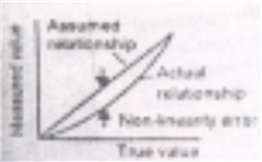
Non-Linearity error
The term non-linearity error is used for the error that occurs as a result of assuming a linear relationship between the input and output over the working range. Few systems have a truly linear relationship and thus errors occur as a result of assuming linearity, For example. with a metal resistance element it might be assumed that the resistance varies linearly with the temperature.
METHODS OF MEASUREMENT
Measurement is concerned with the determination of the value of a quantity.
Some of the most commonly used methods of measurement are though the titles are not exclusive and a particular method may appear under more than one heading:
1. Direct Method
The value of the quantity is obtained directly without the need for calculation from the values of other measured quantities. The measurement of a length by means of a ruler is an example of such a measurement.
2. Indirect Method
The value of the quantity is obtained from measurements of other quantities which are linked to the required quantity by a known relationship. An example of this is the determination of the density of an object from measurements of its mass and volume.
3. Direct Comparison Method
This method is based on the comparison of the value of a quantity to be measured with the known value of the same quantity. An example of this is the determination of a mass by means of a balance which compares the mass, with that of known weights.
4. Substitution Method
With this method the value of a quantity is determined by replacing it by a known value of the same quantity which has been chosen in such a way that the reading by an indicating device is the same for both. This method can be used to determine the value of an electrical resistance by substitution for it known resistances until the same current or balance condition for a bridge is obtained.
5. Null Method
This method of measurement involves bringing to zero a quantity being used as an indicator. An example of this type of method is the Wheatstone bridge for the measurement of electrical resistance where the current through a galvanometer is brought to zero to give the balance condition for the bridge and hence a specified relationship between the resistance being measured and known resistances.
6. Deflection Method
This method of measurement involves the value of the quantity being measured being indicated by the deflection of a moving element or indicating device. An example of this is the measurement of current by a moving coil meter.
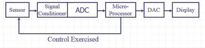
AUTOMATED MEASUREMENT
Microprocessor controlled systems are increasingly being used for the control of the measurement process with instruments. The microprocessor assumes control of the input of data to the instrument and its processing, perhaps controlling the sequencing of measurements made, as well as their processing. The form of the system may be as shown in figure. The input to the microprocessor has to be a digital signal and so an analogue to digital converter (ADC) has to be used. If the display is to be analogue then the output from the microprocessor has to pass through a digital-to-analogue converter (DAC).
I think other web site proprietors should take this site as an model, very clean and magnificent user genial style and design, let alone the content. You’re an expert in this topic!