Architectural Standard Drawings
Partition Details
FIGURE
1 Gypsum Board Partition to 150 mm Above Ceiling
(Non-Fire Rated) ……………………………………………………………
2 Gypsum Board Partition to Bottom of Structure
(Non-Fire Rated)
3 Gypsum Wall Board Partition (Fire Rated – 1 hour and 2 hour)
4 Gypsum Wall Board Partition at Corner
(Fire Rated – 1 hour and 2 hour)………………………………………….5 Concrete Masonry Wall w/ Plaster (Non-Load Bearing)
6 Plaster Control Joint
7
Interior Wall at Roof Slab (Fire Rated – 2 hour)…………………..
8
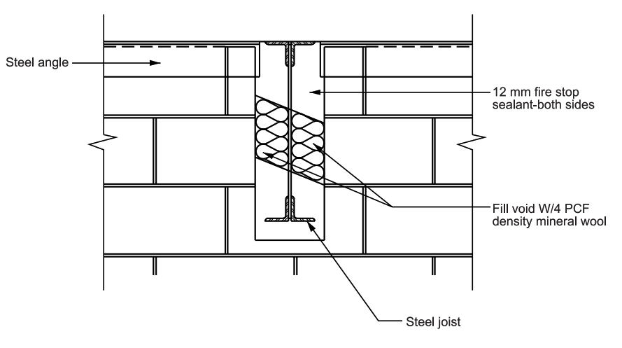
Joist Penetration at Interior Wall (Fire Rated – 2 hour)
Figure 1
Gypsum Board Partition to 150 mm Above Ceiling (Non-Fire Rated)

Figure 2
Gypsum Board Partition to Bottom of Structure (Non-Fire Rated)
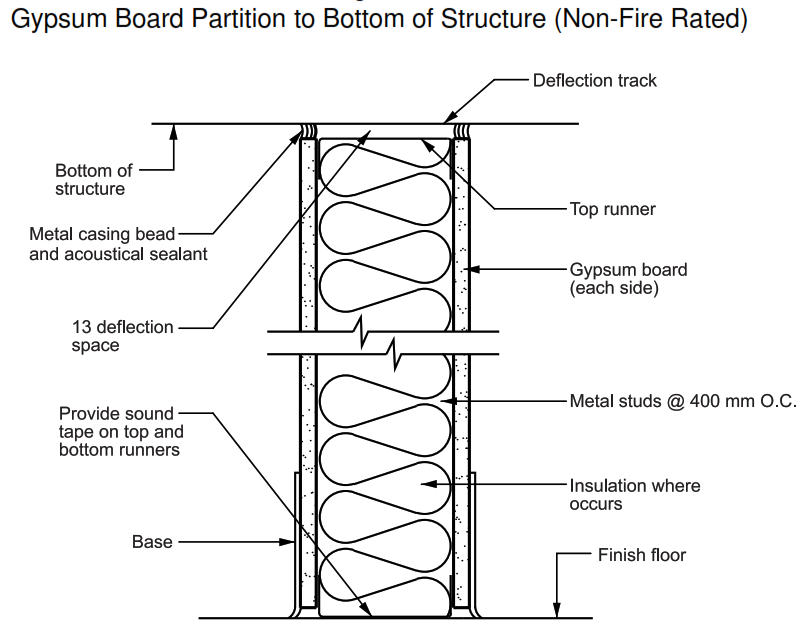
Figure 3
Gypsum Wall Board Partition (Fire Rated – 1 hour and 2 hour)
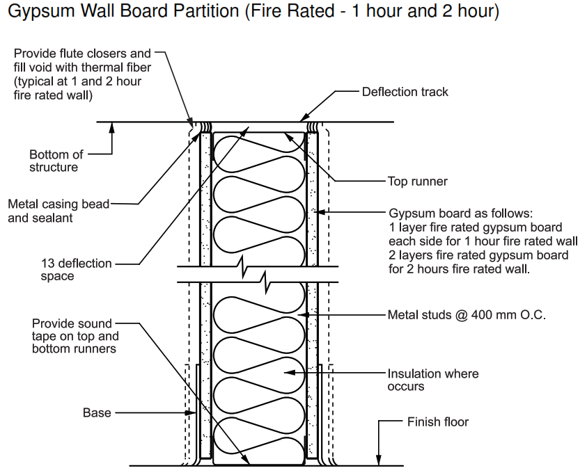
Figure 4
Gypsum Wall Board Partition at Corner (Fire Rated – 1 hour and 2 hour)
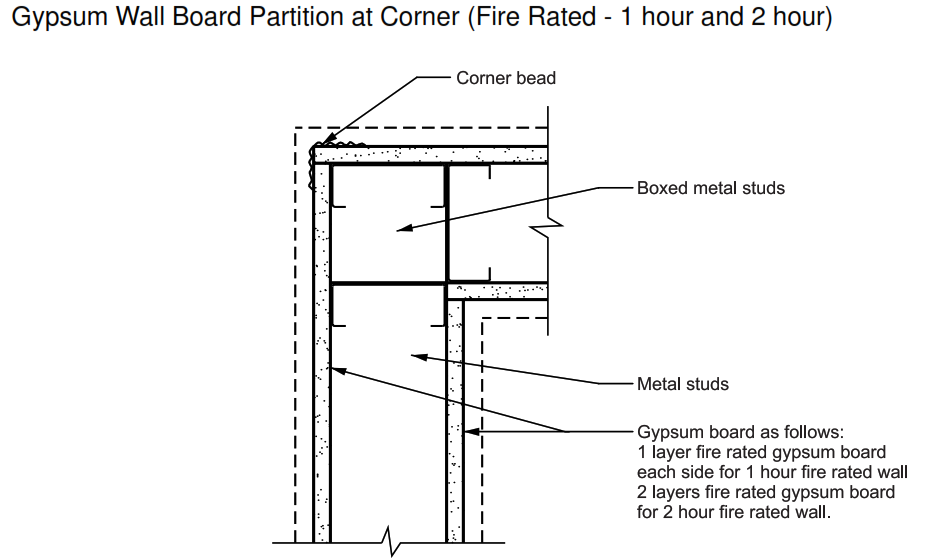
Figure 5
Concrete Masonry Wall w/ Plaster (Non-Load Bearing)
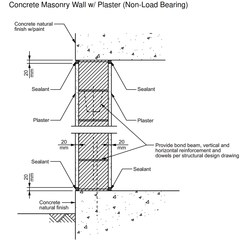
Figure 6
Plaster Control Joint

Figure 7
Interior Wall at Roof Slab (Fire Rated – 2 hour)

Figure 8
Joist Penetration at Interior Wall (Fire Rated – 2 hour)
| Figure 1 | Rake |
| Figure 2 | Ridge |
| Figure 3 | Wall Base |
| Figure 4 | Inside Corner |
| Figure 5 | Outside Corner |
| Figure 6 | Roof and Wall |
| Figure 7 | Small Pipe (4 inch maximum) Roof Penetration |
| PARTITION DETAILS – Architectural Drawings | |
| Figure 1 | Gypsum Board Partition to 150 mm Above Ceiling (Non-Fire Rated) |
| Figure 2 | Gypsum Board Partition to Bottom of Structure (Non-Fire Rated) |
| Figure 3 | Gypsum Wall Board Partition (Fire Rated – 1 hour and 2 hour) |
| Figure 4 | Gypsum Wall Board Partition at Corner (Fire Rated – 1 hour and 2 hour) |
| Figure 5 | Concrete Masonry Wall w/ Plaster (Non-Load Bearing) |
| Figure 6 | Plaster Control Joint |
| Figure 7 | Interior Wall at Roof Slab (Fire Rated – 2 hour) |
| Figure 8 | Joist Penetration at Interior Wall (Fire Rated – 2 hour) |
| DOOR AND WINDOW DETAILS – Architectural Drawings | |
| Figure 1 | Exterior Door Head at Metal Panel and Gypsum Board |
| Figure 2 | Exterior Door Jamb at Metal Panel and Gypsum Board |
| Figure 3 | Exterior Door Head at Metal Panel |
| Figure 4 | Exterior Door Jamb at Metal Panel |
| Figure 5 | Interior Door Head (Jamb Similar) at Masonry and Gypsum Board |
| Figure 6 | Interior Door Head at Masonry |
| Figure 7 | Interior Door Jamb at Masonry |
| Figure 8 | Interior Door Head and Jamb at Gypsum Board |
| Figure 9 | Interior Door Transom at Gypsum Board |
| Figure 10 | Exterior Door Head and Jamb at Concrete and Gypsum Board |
| Figure 11 | Interior Window Head and Jamb at Gypsum Board |
| Figure 12 | Roll-Up Door Head at Metal Panel |
| Figure 13 | Roll-Up Door Jamb at Metal Panel |
| WALL – FLOOR INTERSECTION DETAILS – Architectural Drawings | |
| Figure 1 | Vinyl Tile Floor at Gypsum Board Wall or Metal Liner Panel |
| Figure 2 | Ceramic Tile Floor at Ceramic Tile Wall |
| Figure 3 | Acid Resistant or Epoxy Floor at Ceramic Tile Wall |
| Figure 4 | Acid Resistant or Epoxy Floor at Plaster Wall |
| Figure 5 | Floor Hardener at Gypsum Board Wall |
| FLOOR – THRESHOLD DETAILS – Architectural Drawings | |
| Figure 1 | Threshold – Vinyl to Carpet |
| Figure 2 | Threshold – Vinyl to Concrete |
| Figure 3 | Threshold – Quarry Tile to Vinyl |
| Figure 4 | Threshold – Vinyl to Ceramic Tile |
| Figure 5 | Marble Threshold – Vinyl to Ceramic Tile |
| CEILING DETAILS – Architectural Drawings | |
| Figure 1 | Lateral Bracing Attachment of Acoustical Ceiling Grid |
| Figure 2 | Gypsum Board Soffit / Suspended Ceiling |
| Figure 3 | Acoustical Ceiling Edge |
| Figure 4 | Gypsum Board Ceiling |
| Figure 5 | Light Fixture Support |
| TOILET DETAILS – Architectural Drawings | |
| Figure 1 | Typical Toilet Booth – Masonry (Western and Eastern Toilet) |
| Figure 2 | Plan of Typical Ablution Foot Wash |
| Figure 3 | Section of Typical Ablution Foot Wash |
| Figure 4 | Typical Locker and Benches |
| Figure 5 | Locker Base and Top |
| ACCESS FLOOR – Architectural Drawings | |
| Figure 1 | Access Floor at Exterior Wall |
| Figure 2 | Access Floor at Interior Wall |