Architectural Standard Drawings
Toilet Details
FIGURE
1. Typical Toilet Booth – Masonry (Western and Eastern Toilet)….2.
Plan of Typical Ablution Foot Wash
3. Section of Typical Ablution Foot Wash
4. Typical Locker and Benches …………………………………………….5. Locker Base and Top
6. Water Closets
7. Water Closets (Eastern Type) …………………………………………..8. Service Sink
9. Curb Detail
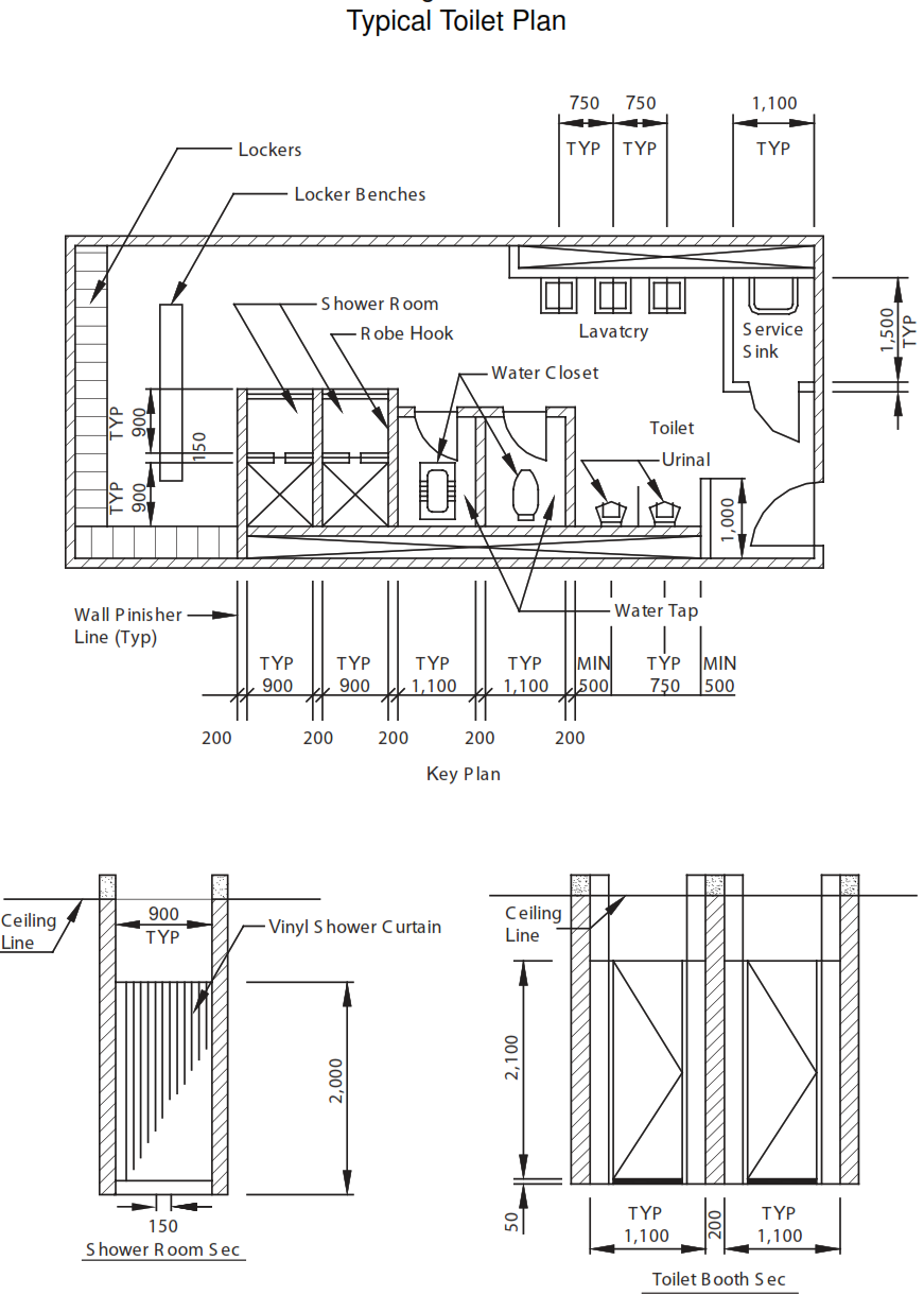
10. Urinal …………………………………………………………………………….11. Lavatory 12. Shower 13. Robe Hook …………………………………………………………………….14. Typical Toilet Plan
Figure 1
Typical Toilet Booth – Masonry (Western and Eastern Toilet)
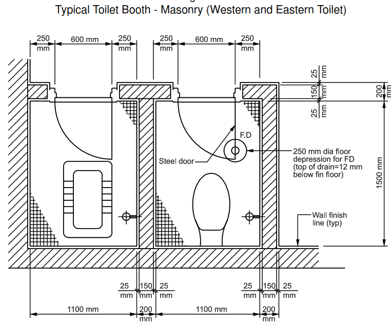
Figure 2
Plan of Typical Ablution Foot Wash
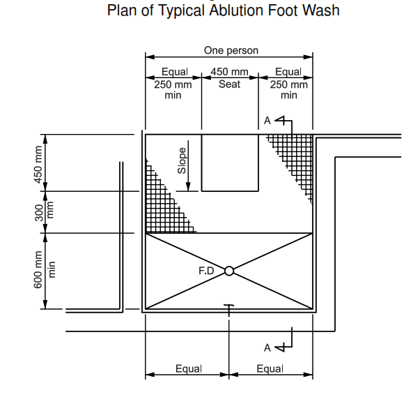
Figure 3
Section of Typical Ablution Foot Wash

Figure 4
Typical Locker and Benches

Figure 5
Locker Base and Top
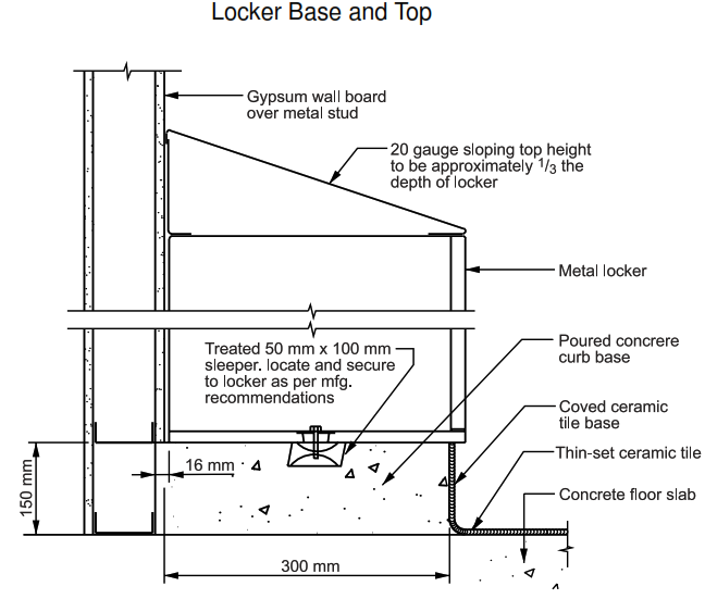
Figure 6
Water Closets
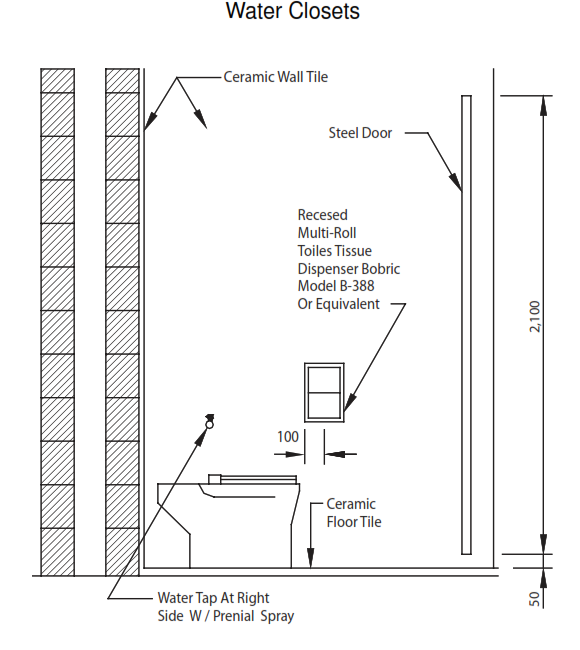
Figure 7
Water Closets (Eastern Type)

Figure 8
Service Sink

Figure 9
Curb Detail

Figure 10
Urinal

Figure 11
Lavatory

Figure 12
Shower

Figure 13
Robe Hook

Figure 14
Typical Toilet Plan
General Notes
1. All Dimensions are in millimeters unless otherwise specified.
2. Urinal screens shall be metal with a baked enamel finish, wall mounted type.
3. Toilet and bath accessories shall be the products of Bobric Wash Room Equipment Inc. or
equivalent
4. Metal lockers shall be 300 mm wide x 450 mm deep x 1.800 mm high (unless noted otherwise
on
the drawings) double tier with sloping top and baked enamel finish of a standard color.
Each locker shall have a coat hook and a number plate.
Door shall be louvered top and bottom with a flat key lock.
Lockers shall be as maufactured by lyon metal products or equivalent.
Locker benches shall be manufacture standard hardwood seat 250mm wide and with enameled
steel bases.
| METAL BUILDING DETAILS – Architectural Drawings | |
| Figure 1 | Rake |
| Figure 2 | Ridge |
| Figure 3 | Wall Base |
| Figure 4 | Inside Corner |
| Figure 5 | Outside Corner |
| Figure 6 | Roof and Wall |
| Figure 7 | Small Pipe (4 inch maximum) Roof Penetration |
| PARTITION DETAILS – Architectural Drawings | |
| Figure 1 | Gypsum Board Partition to 150 mm Above Ceiling (Non-Fire Rated) |
| Figure 2 | Gypsum Board Partition to Bottom of Structure (Non-Fire Rated) |
| Figure 3 | Gypsum Wall Board Partition (Fire Rated – 1 hour and 2 hour) |
| Figure 4 | Gypsum Wall Board Partition at Corner (Fire Rated – 1 hour and 2 hour) |
| Figure 5 | Concrete Masonry Wall w/ Plaster (Non-Load Bearing) |
| Figure 6 | Plaster Control Joint |
| Figure 7 | Interior Wall at Roof Slab (Fire Rated – 2 hour) |
| Figure 8 | Joist Penetration at Interior Wall (Fire Rated – 2 hour) |
| DOOR AND WINDOW DETAILS – Architectural Drawings | |
| Figure 1 | Exterior Door Head at Metal Panel and Gypsum Board |
| Figure 2 | Exterior Door Jamb at Metal Panel and Gypsum Board |
| Figure 3 | Exterior Door Head at Metal Panel |
| Figure 4 | Exterior Door Jamb at Metal Panel |
| Figure 5 | Interior Door Head (Jamb Similar) at Masonry and Gypsum Board |
| Figure 6 | Interior Door Head at Masonry |
| Figure 7 | Interior Door Jamb at Masonry |
| Figure 8 | Interior Door Head and Jamb at Gypsum Board |
| Figure 9 | Interior Door Transom at Gypsum Board |
| Figure 10 | Exterior Door Head and Jamb at Concrete and Gypsum Board |
| Figure 11 | Interior Window Head and Jamb at Gypsum Board |
| Figure 12 | Roll-Up Door Head at Metal Panel |
| Figure 13 | Roll-Up Door Jamb at Metal Panel |
| WALL – FLOOR INTERSECTION DETAILS – Architectural Drawings | |
| Figure 1 | Vinyl Tile Floor at Gypsum Board Wall or Metal Liner Panel |
| Figure 2 | Ceramic Tile Floor at Ceramic Tile Wall |
| Figure 3 | Acid Resistant or Epoxy Floor at Ceramic Tile Wall |
| Figure 4 | Acid Resistant or Epoxy Floor at Plaster Wall |
| Figure 5 | Floor Hardener at Gypsum Board Wall |
| FLOOR – THRESHOLD DETAILS – Architectural Drawings | |
| Figure 1 | Threshold – Vinyl to Carpet |
| Figure 2 | Threshold – Vinyl to Concrete |
| Figure 3 | Threshold – Quarry Tile to Vinyl |
| Figure 4 | Threshold – Vinyl to Ceramic Tile |
| Figure 5 | Marble Threshold – Vinyl to Ceramic Tile |
| CEILING DETAILS – Architectural Drawings | |
| Figure 1 | Lateral Bracing Attachment of Acoustical Ceiling Grid |
| Figure 2 | Gypsum Board Soffit / Suspended Ceiling |
| Figure 3 | Acoustical Ceiling Edge |
| Figure 4 | Gypsum Board Ceiling |
| Figure 5 | Light Fixture Support |
| TOILET DETAILS – Architectural Drawings | |
| Figure 1 | Typical Toilet Booth – Masonry (Western and Eastern Toilet) |
| Figure 2 | Plan of Typical Ablution Foot Wash |
| Figure 3 | Section of Typical Ablution Foot Wash |
| Figure 4 | Typical Locker and Benches |
| Figure 5 | Locker Base and Top |
| ACCESS FLOOR – Architectural Drawings | |
| Figure 1 | Access Floor at Exterior Wall |
| Figure 2 | Access Floor at Interior Wall |