1. Scope: This Article covers limitations on various types of weld joints; including pipe to pipe, pipe to flange, pipe to fitting; used in metallic piping for pressure services in plants and pipelines, and supplements ASME B31 piping codes.
2. References
The selection of material and equipment, and the design, construction, maintenance, and repair of equipment and facilities covered by this specification shall comply with the latest edition of the references listed below, unless otherwise noted.
W05-F02 Welding Requirements
American Petroleum Institute (API)
API SPEC 6A – Wellhead and Christmas Tree Equipment.
API STD 606 – Compact Steel Gate Valves – Extended Body.
American Society of Mechanical Engineers (ASME)
B1.20.1 Pipe Threads, General Purpose (Inch).
B16.25 Buttwelding Ends.
ASME B31G Manual for Determining the Remaining Strength of Corroded Pipelines a Supplement to ASME B31.
B31.3 Chemical Plant and Petroleum Refinery Piping.
B31.4 Liquid Transportation Systems for Hydrocarbons, Liquid Petroleum Gas.
B31.8 Gas Transmission and Distribution Piping Systems.
Section VIII, Div 2 Pressure Vessels, Alternative Design.
3. Definitions
For the purpose of understanding this Article, the following definition applies.
Hazardous Service – Fluid services that are deleterious to human health, or will contribute to a fire, are considered hazardous.
4. Pipe Weld Joints in Plants and Pipelines | ASME B31 Piping Code General Requirements
a. Welded Joints.
b. Flanged Joints.
c. Threaded Joints.
d. Seal Welding of Threaded Joints.
e. Joints for Tubing.
f. Other Joints.
5. Welded Joints
5.1 Pipe Welds
Welds in metallic piping shall conform to the requirements of SES W05-F02 and other Standards referenced therein.
5.1.1 Joints Between Piping of Equal Strength, with Different Walls
The joint details for piping of equal strength, and different wall thickness shall be as follows:
a. When the wall thickness ratio of the two pieces is less than or equal to 1.5, the thicker wall is taper bored in accordance with the respective ASME B31 design code.
b. When the wall thickness ratio of the two pieces is greater than 1.5, a combination of taper boring and weld end preparation is used. The end preparations and geometry shall comply to ASME B16.25.
5.1.2 Joints Between Piping of Unequal Strength, with Different Walls
When pipe materials joined have different yield strengths and unequal wall thicknesses, taper boring and special beveling in accordance with ASME B16.25 under the following is to be used as follows:
a. When the thickness of the lower grade material exceeds 1.5 times the required thickness of the higher grade but is not needed to match the design strength of the higher grade.
b. When the thickness of the higher grade material exceeds 1.5 times the required thickness of the lower grade.
c. When the joint is under the jurisdiction of ASME B31.3, and both walls are the pressure design thicknesses plus the manufacturer’s minus tolerance.
d. When the joint is under the jurisdiction of the ASME B31.4/B31.8 codes, both walls are the pressure design wall thicknesses which already included the under thickness tolerance.
5.1.3 Transition Pieces
When joining pipes of different material grades (yield strengths), a transition piece shall be used if the wall thickness of lower grade material is greater than 1.5 times the wall thickness of higher grade material. Graphic details of the joint designs are shown in ASME B31.3, ASME B31.4 and ASME B31.8.
5.2 Socket Welds
The maximum size of socket-welded joints in hazardous services shall be NPS 2 for new construction. Maximum NPS-2 may be used in hazardous service for maintenance, minor field modifications of existing piping systems, and when necessary to match existing equipment connections. Consideration shall be made for NPS 2 socket welds in Class 900 and higher pressure ratings where high mechanical loads are present, or vibration is present.
5.3 Fillet Welds
Joining two lengths of pipe by means of a fillet weld is permitted only where cement lined pipe is being joined with coupling sleeves.
6. Flanged Joints
6.1 Exclusions
Flanged joints are subject to failure when loaded with external forces, or reciprocating forces. Flanged connections shall be avoided in the services that produce these forces. The most reasonable choice is to use fully buttwelded construction, with flanges only where unaviodable, and with careful stress analysis.
Other joints may be successful, with careful research. Flanged joints shall also be avoided where leaks are not tolerated, or severe hazard exists from leaked fluid. The following services are typical of those where flanges are to be avoided:
a. Steam in ASME Class 900 and higher
b. In the fully restrained portion of cross-country pipelines and in underwater pipelines
c. In locations where the piping will be subjected to large bending or other external loads
d. Buried piping
e. Hydrogen service
6.2 Valve Joints
Valves with pressure seal bonnets, or welded bonnets, should be used to avoid a leak path in valving.
6.3 Limitations on Through Bolted Joints
Flanged connections with long exposed bolts for sandwiched components, other than standard spectacle plates and blinds, shall not be used in fire hazardous areas. Special consideration shall be given to all situations where through bolting is used for more than one component.
7. Threaded Joints
7.1 Hazardous Services
The maximum size of threaded connections in hazardous services shall be NPS-1 1/2 for standard fittings and valves, and 2-inch NPS maximum when required for maintenance, minor field modifications of existing piping systems, and to match threaded specialty devices such as access fittings for corrosion monitoring.
7.2 Non Hazardous Service
The maximum size of threaded connections in non-hazardous services shall be NPS-4 for standard fittings and valves, and NPS-4 maximum on special items such as fire hydrants.
7.3 Standards
The thread standard shall be taper pipe thread conforming to ASME B1.20.1.
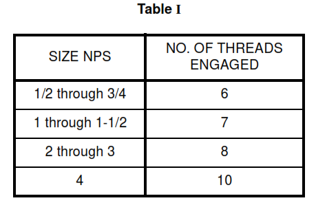
7.4 Thread Engagement
Minimum number of engaged pipe threads shall meet the requirements of Table I , Thread Engagement
7.5 Exclusions
Joints in leak prone services, such as caustic shall not be threaded.
8. Seal Welding of Threaded Joints
8.1 The Seal Weld
Where seal welding is required, the seal weld shall be a fillet weld going from the outer diameter of the female part, smoothly with slight concavity, to the male part covering all exposed threads without undercut.
8.2 General Requirements
Seal welding of threaded joints is required when deemed necessary for those locations and services where an uncontrolled leakage would result in serious consequences for the operation or safety of plant and personnel.
8.3 Special Requirements
8.3.1 When threaded joints cannot be avoided, seal welding shall be applied to all threaded joints, upstream and downstream of the root valve, in the following services:
a. All hydrocarbons
b. Boiler feedwater, condensate, and steam systems utilizing ASME Class 300 and higher flange ratings
c. Toxic materials such as chlorine, phenol, hydrogen sulfide, etc.
d. Corrosive materials such as acid, caustic, etc.
e. Oil field chemicals (e.g. corrosion inhibitors, emulsifiers, electrolytes, etc.)
8.3.2 Exceptions to seal welding include:
a. Thermowells.
b. Bar stock plugs downstream of a seal-welded block valve.
c. Special devices such as access fittings and “scraper flags”.
d. Joints which require frequent disassembly and are located downstream of a seal welded block valve, e.g. sample connections.
e. Instrument piping between the seal welded root valve and the instrument.
f. Pipe union ring threads and joints with elastomer o-rings.
g. Threaded joints, downstream of a seal welded root valve, which discharge directly to an open drainage system or to the atmosphere.
h. Extended body valves with integrally reinforced welding end per API 606.
i. Any material requiring PWHT for service.
8.4 Mechanical Requirements
Seal welding is required on threaded joints when the piping is subject to vibration, whether continuous or intermittent.
8.5 Joint Compound
PTFE (Teflon) tape or joint compounds shall not be used in threaded connections requiring seal welding. PTFE tape shall not be used for service temperature greater than 204 deg C.
9. Joints for Tubing
The use of fittings for flared, flareless, and compression-type tubing fittings for field installations shall be limited to the types and brands listed in the standards. When new construction is taking place in a plant, compression fittings shall be of the same manufacture as those already in use in a plant.
10. Other Joints
10.1 Caulked Joints
Caulked joints shall not be used for any pressure service.
10.2 Soldered, Brazed, and Braze-Welded Joints
Soldered, brazed, and braze-welded joints shall be limited to water and air services.
10.3 Proprietary Mechanical Joints
Proprietary mechanical joints used for non-hazardous pressure services shall be of a design approved, Victaulic couplings and Dresser couplings are typical types.
10.4 Clamp-Type Connectors
Clamp-type connectors for high pressure services shall conform to API SPEC 6A or shall be proprietary connectors of a design based on ASME Section VIII and approved. Grayloc is the most popular example.
10.5 Proprietary Couplings
Proprietary couplings for pipeline repair, such as Plidco, Weld + Ends couplings, proprietary swivel joints, such as Chiksan, or similar specialties shall be of a design approved.