1.0 PURPOSE
1.1. This work procedure and method statement shall provide minimum guidelines to carry out the Aboveground Piping Installation Works activities for piping or mechanical engineers, procedures In accordance with contract scope of work and project specification.
2.0 SCOPE
2.1. This Method Statement covers the procedure of Aboveground Piping Installation Works.
3.0 APPLICABLE DOCUMENTS
- Piping Material Specification
- Identification of Piping Materials
- General Specification for Insulation
- Construction Specification for Installation of Static Equipment
- Construction Specification for Installation of Rotary Equipment
- Construction Specification for Piping Work at Prefabrication Shop
- Specification for Piping Construction Work in Field
- Piping Pressure Test Procedure
- Line Check Scope of work
- Piping Internal Cleaning Procedure
- Bolt Tensioning Procedure
- Piping Spool Drawing Preparation and Weld Joint Registration Procedure
- ISO/Spool Drawing and Data Handling Procedure
- Supplementary Specification for External Coating
- Supplementary Specification for Safety Identification and Safety Colors
- Supplementary to SAES-A-206 Positive Material Identification
- Material and Equipment Protection Program at Work Site
- Detailed Material Control Procedure for Piping Material at Field
- Material Traceability at Site (Construction Phase)
3.2. Saudi Aramco Standard
3.2.1. SAES-L-350 Construction of Plant Piping
3.2.2. SAES-W-011 Welding Requirements for On-Plot Piping
3.2.3. SAES-W-012 Welding Requirements for Pipelines
3.2.4. SAES-H-200 Storage, Handling and Installation of Pipe Externally Coated Pipe
3.2.5. SAES-L-110 Limitation of Pipe Joints and Component
3.2.6. SAES-S-070 Installation of Utility Piping System
3.2.7. SAEP-324 Certification Review and Registration of Project Welders and Brazers
3.2.8. SAEP-1142 Qualification of Non-Saudi Aramco NDT Personnel
3.2.9. SAES-A-206 Positive Material Identification
3.2.10. SAES-A-301 Materials Resistant to Sulfide Stress Corrosion Cracking
3.2.11. 01-SAMSS-024 Pipe Handling and Nesting
3.2.12. SCHEDULE ‘‘Q’’ Quality Requirements
3.2.13. SAEP-351 Bolted Flange Joints Assembly
3.3. Industry Codes Standard
3.3.1. ASME B1.20.1 Pipe Threads, General Purpose
3.3.2. ASME B31.3 Process Piping
3.3.3. ASME B31.4 Pipeline Transportation System for Liquid Hydrocarbons and Other Liquids
3.3.4. ASME B46.1 Surface Texture (Surface Roughness Waviness, and Lay)
3.3.5. ASME B16.20 Metallic Gaskets for Pipe Flanges
3.4. Applicable SATIP/SAIC/SATR
3.4.1. SATIP-L-350-01 SATIP for On-Plot Piping Installation
3.4.2. SAIC-L-2011 Piping Pre-Installation Inspection (Prior to On-Plot Work)
3.4.3. SAIC-L-2012 Pipe Laying, Spool Erection and Assembly on Piperacks and Sleeper ways
3.4.4. SAIC-L-2013 Inspection of Piping Branch Connections
3.4.5. SAIC-L-2015 Inspect Threaded Joint Engagement (Gap Control)
3.4.6. SAIC-L-2017 Piping / Equipment Internal Cleaning Inspection
3.4.7. SAIC-L-2018 Inspection of Pipe Support and Pipe Anchor Installation
3.4.8. SAIC-L-2019 Installation of Buried Piping (UG On-Plot Metallic Piping)
3.4.9. SATR-A-2007 Pre-Test Punch List Form
3.5. Standard Drawing / Latest Revision Documents
3.5.1. Piping and Instrument Drawing (P&ID)
3.5.2. Piping General Arrangement Drawing
3.5.3. Pipe Support Detail Drawing
3.5.4. Isometric Drawing (Full Isometric)
3.5.5. Spool Drawing (Spoolgen Generated)
4.0 RESPONSIBILITY
4.1. Construction Manager shall implement all HSE requirement for the job, study, analyze and schedule all construction activities with his department to include manpower and equipment line up as well as other possible resources required for the successful implementation of the construction work activities. He shall study all aspects of work procedure as per Technical Scope of Work.
4.2. Piping Superintendent shall study and review all necessary documents for the installation works to include, technical scope of work, specification, bill of quantities, planned milestone dates and construction procedure to support to his supervisor. He shall monitor the availability of materials in accordance with construction schedules. He shall directly report to construction Manager.
4.3. Piping Supervisor shall be directly reporting to the Piping Superintendent and responsible for the implementation and control of all site activities per Technical Scope of Work and latest approved construction drawings. He shall coordinate with other discipline to visualize possible conflicts in the drawing as well as in the schedules to provide other options in preventing unnecessary delays and obstructions.
4.4. The Welding Supervisor and Foreman are solely responsible to ensure that all welding works are in conformance with applicable codes, standards, specifications and approved procedures.
4.5. Piping Foreman shall be responsible for the direct work supervision at site and ensure that the work is performed in accordance with Technical Scope of Work and latest approved for construction drawings. He shall monitor the availability of materials in line with his required schedule at site and reports directly to Piping Supervisor.
4.6. QC Inspector shall be responsible for inspection and monitoring of the work and ensure that the work is performed and properly documented in accordance with Project requirements.
4.7. Safety Supervisor shall be responsible for monitoring safety aspects and ensuring that the work is done in accordance with Safety Standard Procedure. He shall discuss with the workers the characteristics of related materials and status of work area giving reminders as an additional point to work safely.
5.0 MANPOWER
5.1. The Piping Superintendent shall control the overall activity of Piping Aboveground Installation Works. The basic manpower under him shall consist but not limited to the following:
5.1.1. Piping Supervisor
5.1.2. Piping Foreman
5.1.3. Welding Foreman
5.1.4. Pipe fitters
5.1.5. Welders
5.1.6. Crane Operator (ARAMCO Certified)
5.1.7. Rigger (ARAMCO Certified)
5.1.8. Helpers
5.2. Safety Engineer/Officer
6.0 TOOLS AND EQUIPMENT
6.1. Tools and equipment needed should be in good condition and must be checked by Piping Supervisor / Safety Officer prior to use in the construction area. These includes but not limited to:
6.1.1. Tools, Jigs, Instruments
6.1.1.1 Ball Hammer
6.1.1.2 Wrenches
6.1.1.3 Magnetic/Spirit Level
6.1.1.4 Fillet Gauges
6.1.1.5 Dial Indicator
6.1.1.6 Pipe Jack Stands
6.1.1.7 Chain Block/Puller
6.1.1.8 Pulley
6.1.1.9 Cable
6.1.1.10 Flange Jack
6.1.1.11 Feeler Gauge
6.1.1.12 Bevel Gauge
6.1.1.13 T-Square
6.1.1.14 Straight Edge
6.1.1.15 Hi-Lo Gauge
6.1.1.16 Internal Flange Alignment Tool
6.1.1.17 WrapAround
6.1.2. Equipments
6.1.2.1 Mobile Crane
6.1.2.2 Forklift
6.1.2.3 Welding Machine
6.1.2.4 Threading Machine
6.1.2.5 Hand Grinder
6.1.2.6 Pencil Grinder
6.1.2.7 CuttingOutfit
6.1.2.8 Boom Truck
6.1.2.9 Generator Set
6.1.2.10 Trailer Truck
6.1.2.11 Pipe Roller
7.0 MATERIAL RECEIVING, STORAGE AND PRESERVATION
7.1. Material Receiving
7.1.1. Piping materials delivered shall be checked and inspected in accordance with applicable SAIC and JGC Specification no. S-000-3160-002 Section 4.0.
7.1.2. Ascertain materials by checking the stencil, color code etc. prior to use of material.The size and rating shall conform to the related drawing and/or specifications. SAACO shall be responsible for keeping all vendor markings and other identifying information after receiving of the material. When a length of pipe is cut from a longer pipe, SAACO shall transfer to
each length of pipe all vendor markings including heat number and other identifying information.
7.2. Material Handling / Storage
7.2.1. All materials shall be handled with care during installation to prevent damage.
7.2.2. Wide fabric slings shall be used for lifting lined and coated pipe and fittings to prevent damage as per SAES-H-200.
7.2.3. Special attention shall be given to protection of flange(s) faces to preventany damage, by ensuring that flanges received from awarehouse are properly protected. Stainless steel and non-ferrous alloy pipe / fitting shall be stored and handled with special care to avoid any contamination and should be kept away from carbon steel material including carbon steel grinders, blush and the likes.
7.2.4. Flange face serration shall be made as per S-000-1360-003 (FlangeFacing Finish) or piping engineer to approve at site, if flange face damaged.
7.2.5. Pipe shall be placed on any type of dunnage. Pipe shall not be stored directly on the ground.
7.2.6. Stacking of pipe shall be made in accordance with vendor preservation procedure to avoid damage to pipes or coating.
7.2.7. End protectors on pipes, flanges, any fittings, weld bevels, threads, and socket ends shall be firmly attached.
7.2.8. Contamination between carbon steel, stainless steel and non-ferrous alloy shall be avoided.
7.3. Material Preservation
7.3.1. Pipes, valves and fittings shall be internally and externally cleaned and be checked for any defects and damages. Any damage and defects shall be promptly reported to authorized designated personnel.
7.3.2. Preservation shall be in accordance with manufacturer’s recommendation and Specification(S-000-1630-003 : Material and Equipment Protection Program at Work Site).
7.3.3. Piping internal cleaning shall be in accordance with specification (S-000-3160-007 : Piping Internal Cleaning Procedure)
8.0 GENERAL REQUIREMENTS
8.1. Isometric and Spool Drawing Preparation
8.1.1. Detail Drawing
8.1.1.1 Spool erection drawing and spool piece drawing shall be prepared. Only in case of any changes in ISO drawing such as Revision ISO and FS (Field Modification), SAACO shall revise in accordance with specification S-000-3160100,Piping Spool Drawing Preparation and Weld Joint Registration Procedure. when revision of spool erection drawing and spool piece drawing by are required.
8.1.1.2 The latest revision of approved IFC drawings shall be used.
8.1.2. Fabricated Piping Piece Maximum Dimension
8.1.2.1 The maximum dimension of fabricated piping pieces shall be limited to as follows :
3.5m (H) x 14.0 m (L) x 2.4 m (W)
Note : Above dimension limitation shall be also applicable to piping spool with internal lining.
8.2. Qualification of Welder/Welding Operator
8.2.1. Qualification of welders/welding operators shall follow the requirements and instructions in SAEP-324 regarding certifications and qualification of welders.
8.3. NDT/PWHT Requirements
8.3.1. NDT personnel shall follow the general requirements, training, qualification examinations and certification as per SAEP-1142, Qualification of Non Saudi Aramco NDT Personnel.
8.3.2. NDT/ PWHT requirements shall be in accordance with S-000-1360001 Attachment 4, S-000-3160-002 Attachment 6 and each Isometric and Spool Drawings.
8.4. Field and Installation
8.4.1. Internal Lined Piping (Line Class : xxLExxx)
8.4.1.1 There is no field weld for internal lined piping for this project basically.
8.4.1.2 Precaution not to heat on the spool (avoid damage of lining). Flange connection should be done with proper procedure as per para 9.5.
8.4.1.3 Maximum 6 meters to 12 meters length from open end depending on pipe size can be allowed for application of internal lining on girth welding point. Welding point to be lined shall be located within a certain length from open end. Welding point of internal lining work shall be hand-over to other party. Erection of next spool shall be after inspection of lining on the point is acceptable. This condition shall be applicable for the piping system which has internal lining, but not to the others.
8.4.2. Stainless steel Material Fabrication (Line Class: xxSDxxxx)
8.4.2.1 Working tools for stainless steel including cutting, grinding and buffing discs, wheels, or brushes shall be intended for stainless steel work and shall be easy to recognize by means of color coding or tape marking, recommended color is red. Tools such as grinding wheels and wire brushes previously used on carbon steel shall not be used on stainless steel or nickel alloy materials. Only 300 series stainless steel brushes shall be used on austenitic and nickel alloys. (Ref. PFI Standard ES-43 para.3.2 & 3.4)
8.4.2.2 Straight pipe cutting and pipe end preparation shall be carried out using plasma or mechanical cutting. Cleaning shall be applied when there is scale on surface.
8.4.2.3 Segregate pipe spool from other materials when temporary laid down at job site or at fabrication shop prior to erection or fabrication.
8.4.2.4 Approved marking materials shall only be used for Stainless steel. Any marking or color coding shall be done with materials having a water soluble chloride content not exceeding 50 ppm, measured after the marking materials has dried. (Ref. PFI Standard ES-43 para 4.2)
8.4.2.5 Back purging shall be maintained until at least 10 mm of the weld deposit thickness has been completed. The use of nitrogen as a backing gas for austenitic stainless steels is prohibited.
8.4.2.6 Sponge jig shall be used to keep back seal gas inside. Obtain approval from JGC if other kinds of material are used like soluble purge dam paper, PVOH film. The kind of Item shall be filled in Daily Welding Report (DWR).Refer to S-000-3160-002.
8.4.3. Cutting disk or flame cutting shall be used for cutting carbon steel pipes, beveling is also acceptable only flame cut bevels shall be ground to a smooth finish, nicks and grooves in the bevel are not allowed.
8.4.4. For low alloy steel, Flame cut or mechanical means such as cutting disk are acceptable. After flame cutting, approximately 1.5mm of material must be removed from the surface of beveling by grinding.
8.4.5. Joint Fit-Up/Welding
8.4.5.1 Butt Joints
8.4.5.1.1 Prior to welding check for cleanness of inside piping, cleanliness of groove, alignment of piping and bevel angle and root face for any deficiencies.
8.4.5.1.2 Assure for suitable screen or shelters for protection from weather. Welding work shall not be done in case of rainy and storm winds.
8.4.5.1.3 Unless specified otherwise in the qualified welding procedure, a root gap of about 3 mm shall be required for joints (including branch connections). One exception is that where the pipe wall thickness is less than 4.5 mm, a 1.5 mm root gap shall be used with tolerances of +1.5 mm and minus zero. No gap larger than 1.5mm, measured before welding, shall exist between the periphery of a reinforcing pad and the pipe to which it is attached. Internal misalignment of butt joints shall not exceed 1.5 mm.
8.4.5.1.4 GTAW process shall be used for piping and set-in fittings less than 25.4 mm nominal pipe size for all passes thru butt welding.
8.4.5.1.5 GTAW process shall be used for the root pass of butt welds without backing in piping and set-in fittings of 50.8 mm nominal pipe size or less, except for vent and drain piping open to the atmosphere.
8.4.5.1.6 GTAW process shall be used for the root pass of single-sided groove welds without backing made with stainless steel or nickel-based consumables.
8.4.5.1.7 Assure that welding procedure strictly adhers to the applicable Welding Procedure Specification.
8.4.5.2 Socket Joints
8.4.5.2.1 Gap control for socket weld shall be in accordance with (Special Process Procedure for Gap Control for Socket Weld and Back Welded Theaded Fittings).
8.4.5.2.2 The axial gap between male and female component shall be maximum of 3mm and minimum of 1.5 mm refer to S-000-3160-002 section 6.4.2
8.4.5.3 Threaded Piping
8.4.5.3.1 Prepare cutting and threading equipment and tool for each type of materials, thickness and diameter range. Cutting and threading tools used for carbon steel shall not be used for cutting stainless steel pipes to prevent contamination.
8.4.5.3.2 Tools for carbon steel pipes shall be color- coded to avoid mix-up use with stainless and non-ferrous alloy steel pipes.
8.4.5.3.3 Before cutting, ensure correct cutting lines are marked on pipe according to spool drawings.
8.4.5.3.4 The minimum length of the engaged threads pipe shall meet the requirements of ASME B1.20.1 for taper pipe thread. The minimum number of engaged pipe threads shall meet the requirements of Table 1 of SAES-L-110 “Limitations on Pipe Joints and Components”.
8.4.5.3.5 If seal welding is required for threaded connections, it shall adhere to the requirements specified in Para.8 of SAES-L-110.
8.4.5.3.6 If seal weld is not required for design temperature of 400°F (204°C) and below use loctite or PTFE joining tape or approved joining compound.
8.4.5.3.7 Design temperature of above 400 °F (204 °C) shall be Seal weld wherever possible, otherwise jointing compound must be applied after JGC’s approval.
8.4.5.3.8 Threaded plugs on hydrostatic vents, not provided with a valve, shall be seal welded after testing has been carried out.
8.4.5.3.9 Sealing compounds or tapes shall not be used on joints that are to be seal welded.
8.4.5.4 Tolerances
8.4.5.4.1 For fabricated piping the dimensional tolerance shall be limited to the value.
8.4.5.4.2 Piping 3 inches nominal pipe size and above and connected to machinery/equipment, flange alignment shall be within the following limits.
8.4.5.4.2.1 Vertical bolthole offset of ± 2.4mm
8.4.5.4.2.2 Horizontal bolthole offset of ±2.4mm
8.4.5.4.2.3 Rotational offset of ±2.4mm
8.4.5.4.2.4 Flange face tilt across diameter:
0.025mm per 25 mm (0.001 inch per inch) of flange outside diameter up to a maximum of 0.672 mm (0.030 inch), and 0.254mm (0.010 inch) for all flanges with an outside diameter less than 10 inches.
8.4.5.4.2.5 Flange face separation, gasket thickness: ± 1.6 mm.
8.4.5.4.2.6 Combination of vertical, horizontal and rotational offset: ± 3.2 mm.
8.4.5.5 Prior to fit-up, pipe materials for spool field fabrication shall be checked for traceability marking and ensure the materials are in accordance with the approved spool/isometric drawing.
8.4.5.6 Pipe to be welded shall be fixed with the use of jigs, clamps or direct tack welding. Tack welding and/or full welding shall be qualified according to the approved applicable WPS.
8.4.5.7 Tack welds shall be of sufficient size to maintain joint alignment. The recommended tack thickness shall be 3.2-4.8mm and length shall be 12.5-25.4mm. The minimum number of tack welds shall be :
8.4.5.7.1 Pipe diameter of 101.6mm or less : three (3) equally spaced tacks.
8.4.5.7.2 Pipe diameter above 101.6mm minimum of four equally spaced tacks. The designated inspector should determine if more tacks are needed.
8.4.5.8 Bridge tack ( located above the root area) are acceptable.
8.4.5.9 Temporary weld attachments for temporary handling and support shall be subject to JGC’sapproval and shall be removed according to an approved procedure and ground flush with the base material subject to non-destructive testing (magnetic particle or Dye Pentrant). These temporary attachments shall be made with compatible material.
8.4.5.10 Flange face surfaces shall be protected during fit-up by putting suitable cover/duct tapes to meet acceptance criteria.
8.4.5.11 Bolt holes of flange joints shall be installed to be symmetrical against the vertical and horizontal center-line of the pipe and
shall match the orientation of the matting flange, unless otherwise indicated on the relevant drawings.
8.4.5.12 For large flanges,flange jack shall be used when lifting is needed. 8.4.5.13 Pipe spool open ends shall be protected with end caps where dirt, dust and other foreign objects will be prevented from getting inside the pipe spools. In addition, pipe ends shall be invariably protected at all times.
8.4.5.14 Flattening of bends, measured as the difference between the largest and the smallest outside diameter at any cross section, shall not exceed 5% of the nominal diameter of the pipe. Flattening of bends at weld ends shall not exceed 3% of the nominal pipe diameter.
8.4.5.15 SAACO piping inspector shall verify and document work compliance prior to welding of spools where the following is applicable :
8.4.5.15.1 Bevel angle, root opening and tackweld shall be in accordance with the approved WPS and ASME B31.3 Section 328.4.2 and 328.4.3.
8.4.5.15.2 All surfaces to be welded shall be clean and free from paint, oil, dirt, scale and foreign material detrimental to welding as specified in ASME B31.3 Section
328.4.1. 8.4.5.15.3 Alignment of pipe inside surface shall be within the dimensional limits of approved WPS and ASME B31.3 Para. 328.4.3.
8.4.5.15.4 Weld seams shall be staggered and located in such a way that they shall not intersect openings and external attachments.
8.4.5.15.5 Foreign materials inside the pipe shall be removed.
8.4.6. Pipe Spool Painting
8.4.6.1 Painting work shall be done in accordance with S-000-13A0-001.
9.0 METHODS / PROCEDURE
9.1. Pipe Installation on Pipe Rack
9.1.1. Prior to installation/erection, bellow 30 inches diameter pipes shall be internally cleaned by air blowing, 30 inches and above pipe diameter shall be cleaned by manual such as rags or cloth, sweep cleaning shall be applied instead of air blowing. All prefabricated pipe spools shall be visually inspected for cleanliness, any matter or debris found inside the pipe line shall be removed. Piping Internal cleaning procedure shall be in accordance with JGC Specification (S-000-3160-004 : Piping Pressure Test Procedure)
9.1.2. Piping end shall be covered after inspection and care shall be exercised during installation/erection to prevent damage. Cover end of piping until fitup of joint to succeeding pipe section as per SAES-L-350 sect.15.2.
9.1.3. Prior to installation/erection on pipe rack structure, the following shall be served using authorized bench mark
9.1.3.1 Center line of pipe shall be put on the beam.
9.1.3.2 Coordinates of interface point shall be checked.
9.1.3.3 Pipe spools to be erected on pipe rack structure shall be erected to position using crane and chain blocks to facilitate pulling/moving of pipe spools to inner portion of the pipe rack steel structures and piping around equipment as applicable. Use only nylon sling for erection of coated pipes and pipe supports.
9.1.4. Erection of random pipes shall start from the opening end of the pipe rack structure’s shall be erected to position using crane, pipe rollers and chain block to facilitate of pulling/moving of random pipes at the inner portion of the pipe rack steel structures. Use only nylon sling for erection of coated pipes.
9.1.5. Erection/installation of 24 inches and above internal lining spool on pipe rack structure shall start from the spool with stopper support.
9.1.6. Piping Installation Scheme Using Pipe roller at any applicable Piperack.
9.1.6.1 Pipes will be loaded using cranes into the extended scaffolding at the designated/end of piperack or side loading if possible.
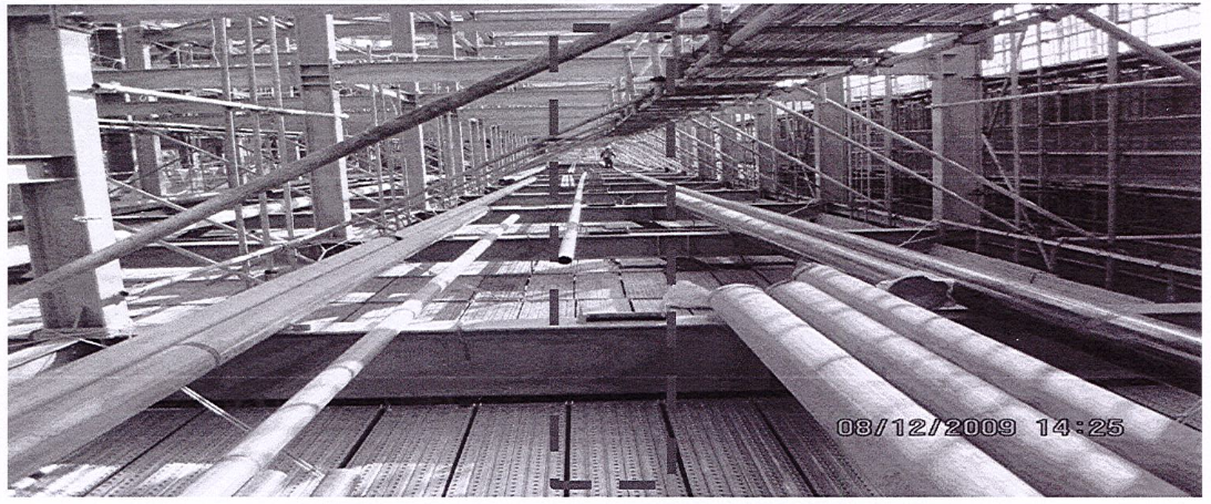
9.1.6.2 Install extended scaffolding at designated loading area at first level. Once the erection of pipes at this level was completed, additional extended scaffold will be installed for the next elevation. Additional hanging scaffold with access walkway will be installed for fit-up and full welding of pipe joints and supports not accessible by the hanging mat scaffold.
9.1.6.3 Install, align and fix the pipe roller assemblies at rack beams. Pipe rollers will be employed primarily to move random lengths along the racks.
9.1.6.4 Install pulley complete with pull cable. The pulley and cable will be used to pull the pipes from loading end, along the pipe rollers, and to its final location.
9.1.6.5 Cranes will pick up the pipes either directly from trailers or from temporary lay down nearby the pipe rack.
9.1.6.6 Pipes will be lifted by cranes using correct nylon slings and will be rig to position at pipe rollers in working platform.
9.1.6.7 Welding together of 6.0m random lengths to make 12m can be done optionally at ground level. RT shall be carried out on ground after double jointing (as applicable).
9.1.6.8 Once the pipe is initially positioned at pipe rollers (two spans), hook the pipe to a pull cable. A special hook attachment will be used so as not to damage bevel at pipe ends.
9.1.6.9 While the pipe is being pulled, a watcher will check the travel of pipe such that it will safely and correctly ride the succeeding pipe
rollers. A signaling system for safe execution and control of pulling will be employed.
9.1.6.10 Once the length of pipe reaches its destination, it will be remove from pipe rollers using chain blocks.
9.1.6.11 Succeeding pipe lengths will be brought to its designated position.
9.1.6.12 Pipe spools such as expansion loops, branch take-offs and others will be placed directly in position using cranes and/or chain blocks where required. Fit up and welding of spooled pieces will be done in place utilizing the mat type scaffold or localized scaffold.
9.1.6.13 For pipelines without attachments, a double-ended welding execution will be adopted- i.e. the first two random length rigged to position will be fitted up and full welded together. The succeeding lengths will be installed in the same manner. The double-ended lengths are then welded together until the entire run is completed. RT shall be carried out on the ground after double jointing (as applicable).
9.1.6.14 At interconnecting pipe racks, the same roller system will be utilized where new steel works is installed and when there are no obstructions.
9.1.6.15 For piping sequence see attached attachment 2.
9.2. Piping Installation Around Equipment
9.2.1. Erection of pipe spools shall start from static equipment nozzles where spool flanges are fitted to equipment nozzle flanges. Do not tight the bolt on rotary equipment flange and pipe unless witnessed or checked by rotary Supervisor.
9.2.2. Blind spade/gasket shall be installed between equipment nozzle and pipe spool in order to avoid contamination until completion of piping pressure test.
9.2.3. Piping installation shall be conducted after receiving of “Work Release Notice” from mechanical section.
9.2.4. It shall be confirmed whether the flange faces for inlet and outlet nozzles of the rotary machine are free from damage and distortion. The flange facing shall be judged by visual comparison with a comparison block of Ra Standards conforming to ASME B46.1.
9.2.5. Temporary gasket shall be inserted between flange face and nozzle of the rotary machine so that necessary space between them can be kept.The temporary gasket shall be a blind gasket to avoid entry of foreign materials into the rotary equipment and also shall be made of soft materials such as sheet gasket to avoid any damage to the flange face. It shall be kept in position until final flange alignment. The size of temporary gasket shall be wider than flange dimension.
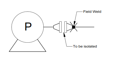
9.2.6. Field welding which affects the alignment of the rotary machine nozzle flange and piping flange shall be done by a method enabling the minimization of distortion due to welding. The rotary equipment nozzle flange and piping flange shall be isolated during field welding, do not install bolt and nuts.
9.2.7. Heat by welding and PWHT on first piping nozzle flange shall not transfer to the flange of equipment.
9.2.8. The final flange alignment of piping connected to rotary machines shall be conducted after all items of piping work including pressure tests, cleaning work, etc. are completed.
9.2.9. Remove all temporary supports. Spring supports shall be kept in a fixed condition.
9.2.10. All protective covers and plugs on the equipment nozzles shall be maintained until the piping is ready to connect to the nozzle.
9.2.11. Welding on piping connected to equipment is not allowed unless the welding machine ground lead is connected directly to the part being welded. This is to avoid damage to the equipment by stray electrical currents.
9.2.12. Pipe flange faces connecting to the primary flange of rotating equipment shall be aligned and within the limits or tolerance.
9.2.13. Proceed to initial tightening of flange bolts in snug-tight condition using hand wrench. Tightening of bolts shall be done in accordance with SAEP351
section 7.
9.2.14. After initial alignment the rotary machine nozzle and piping shall be disconnected from each other and checked to confirm that the tolerances are adhered to.
9.2.15. If specified tolerance is not satisfied, loosen piping flanges from the equipment so correction shall be made to piping or supports.
9.2.15.1 Adjust the piping supports.
9.2.15.2 Adjust the flange connection of the piping in combination with the method.
9.2.15.3 Adjust the piping by cutting and re-welding of appropriate portion of the piping. Hydrostatic test or equivalent test shall be made for the concerned piping spool.
9.2.15.4 Proceed with above steps until the required shaft movement is attained and hand bolting is finalized.
9.2.15.5 After confirmation of the final flange alignment, permanent gaskets shall replace temporary ones and all flange bolts shall be equally and fully tightened with sufficient care.
9.2.16. After final bolt-up, final shaft alignment shall be verified and the equipment shall be hand rotated to ensure that neither binding or case distortion has occurred during piping installation.
9.3. Piping Installation at Pipe Sleeper
9.3.1. Piping instalallation at pipe sleeper and other areas shall utilize cranes or manual rigging method (sticking-out method) to directly install the spool and straight lengths into position.
9.4. Installation of Pipe Support
9.4.1. Pipe supports, anchors, pipe guides, and shoes, etc. shall be installed in proper position in accordance with relative drawings such as standard support drawings, ISO drawing and spool drawing. Refer to S-000-3160002 section 6.7 for Pipe Support Construction Requirements.
9.5. Flange Joint Tightening
9.5.1. Gasket Installation
9.5.1.1 The gasket shall be verified for correct type, rating, dimension and compatibility with the flange facing.It shall be free from any damage particularly in the seating element.
9.5.2. Manual Torque
9.5.2.1 When flange bolts are tightened, the alignment of the center-line and parallelism of the flange faces shall be checked, and all the bolts shall be tightened equally with sufficient care.
9.5.2.2 Lubricant for bolts and nuts shall be Jet-Lube SS-30 or other acceptable lubricants.
9.5.2.3 Select the correct size and hex / socket of torque wrench as applicable.
9.5.3. Hydraulic Torquing / Tensioning
9.5.3.1 Hydraulic Bolt Tensioning requires a specialist skill. Only operatives trained and competent person to use the equipment and up to the standards shall carry out the controlled breakout/assembly and tightening of bolted flanged connections. Subcontractor for hydraulic bolt tensioning shall be approved by Company.
9.5.3.2 Set the torque value on the console by setting the Torque Control Knob according to the desired bolt torque for tightening or loosening as applicable.
9.5.3.3 Bolt tensioner shall be used.
9.5.3.4 All flanges and bolt shall be prepared and pre-assembled prior to tensioning.
9.6. Pressure Testing and Lay-up
9.6.1. Approved test package shall be made available for reference in setting up the pressure test of line or system.
9.6.2. Prior to test, weld lines shall be thoroughly dry, cleaned of rust, grease, paint, or other contaminants
9.7. Touch-Up and Coating
9.7.1. The touch-up and repair of coated surfaces at construction site shall follow Table A of S-000-13A0-001 “Supplementary Specification for External Coating”.
9.7.2. External coating schedule for underground piping shall be referred to the individual data sheets, piping line index.
9.8. Insulation (by other sub-contractor)
9.8.1. Insulation shall be protected from moisture and rain at all times. Installed insulation shall be dry prior to application of weather proofing jacketing or mastic, refer to specification no. S-000-1390-001 General Specification for Insulation,
9.9. Restoration
9.9.1. Remove all temporary items that are installed duringTesting.
9.9.2. Items that were removed during testing shall be reinstalled. Items such as instrument air tubing, check valves disc which were disconected before testing shall be re-connected.
9.9.3. Inspect restoration of piping system, verifyre-assembly and flow arrow direction of valves and othermiscellaneous components where applicable.
10.0 QUALITY CONTROL
10.1. SAACO QC personnel shall be assigned to ensure the quality control andassurance requirement of the project.
10.2. SAACO QC Inspector shall coordinate with other inspectors to conduct inspection as required in SATIP Piping Above ground Installation Works.
10.3. SAACO QC Inspector shall be responsible to conduct all requiredinspections/documentation and to ensure that all applicable requirements, codes,and standards are complied with.
10.4. Contractor has to utilize the applicable SAIC for every activity.
10.5. Mill test reports for the structural materials are furnished and verify confirmation to the requirements of the applicable specification.
10.6. Full traceability of piping and structural shall be done in accordance to schedule Q and JGC Specification (S-000-1630-011 : Material Traceability at Site (Construction Phase))
10.7. Calibration shall be done as required for all machines and tools going to be used in the work in accordance with schedule Q.
10.8. Selection of gasket shall be done in accordance with ASME B16.20.
11.0 SAFETY PRECAUTION
Obtain the approval of the work permit from the concerned JGC Representative before starting any work.
11.1. Fire Watcher with Fire Extinguisher shall be at work area whenever there is hot work. Fire Watcher remains on welding area for 30 minutes after welding is complete.
11.2. All electrical tools shall be checked and color-coded.
11.3. Fire Points on all levels by access tower. Plastic drums shall be provided with buckets are to be marked with the word “Fire”
11.4. Continuous monitoring and inspection shall be implemented to detect and correct unsafe practices while performing the work activities.
11.5. Provide warning sign and sufficient barricade on working area and only assigned personnel will be allowed in the area.
11.6. Welding location shall be enclosed with wind barrier and provided with non asbestos fire blanket to prevent spread of any welding sparks.
11.7. Safety harness with double lanyards shall be used all the time when working at elevated temporary platforms 1.8 meters high and above.
11.8. Man lift users shall be trained and certified to operate and use the equipment.
11.9. Safety Supervisor shall monitor the work activities to help and to protect all assigned workers against exposure to safety hazards. He shall ensure that Personal Protective Equipment (PPE’s) are supplied by Supervisor and used and comply with JGC applicable standards.
11.10. All rigging equipment shall be in good condition and possess a valid certification from authorized certifying and inspection department inspection and color coding shall be done in accordance will JGC inspection guideline.
11.11. Toolbox meeting shall be conducted by Piping Supervisor daily so as work activities will be properly coordinated to all concerned and all safety infractions will be acted immediately.
11.12. Good housekeeping shall be maintained and working area shall be kept in a clean and tidy manner.
11.13. Job Hazard and Risk Assessment (JHRA) of this method statement shall be disseminated and explained to workers prior to start of work
11.14. Safety Requirements for Scaffolding shall be obtained during construction of Scaffolding . A JSA or JHA is required.

PIPING ERECTION SEQUENCE USING PIPE ROLLER AND CHAIN BLOCK METHOD


PIPING ERECTION SEQUENCE USING PIPE ROLLER AND CHAIN BLOCK METHOD

RIGGING PLAN FOR ERECTION OF PIPE SPOOLS

1. POSITION THE CRANE AT ITS DESIGNATED LOCATION AS SHOWN.
2. TRAILER SHALL MOVE BACKWARDS TO PICK-UP POINT AS SHOWN
3. PIPE SPOOL SHALL BE PICKED-UP BY THE CRANE 10M WORKING RADIUS.
4. BOOM-UP TO 7M W.R. THEN PIPE SPOOL SHALL BE STICKED-IN INTO THE PIPERACK.
5. WHEN LOAD IS ALREADY STICKED-IN INTO THE PIPE RACK SLOWLY BOOM DOWN TO 14M W.R. AS THE PIPE SPOOL MANUALLY MANEUVER FOR ALIGNMENT ALONG WITH THE PIPE RACK.
6. SLOWLY HOIST DOWN PIPE SPOOL THEN MOVED TO ITS FINAL COORDINATES AS SPECIFIED ON THE ISO DWG.
NOTE:
1. ALL DIMENSIONS ARE IN MM. UNLESS OTHERWISE NOTED.
2. SECURE LOAD WITH 2 TAG LINES FOR LIFTING.
3. REFER TO RATED LOAD CHARTS FOR CRANE CAPACITIES.
4. MAX. WIND SPEED SHALL BE 12.8 MPS.
JOB SAFETY ANALYSIS FOR PIPING ABOVE GROUND INSTALLATION
Piping Above Ground Erection Sequence

