1. SCOPE……………………………………1.1
Reinforcement
1.2
Stress Intensification Factors
2. REFERENCES…………………………3. DEFINITIONS
4. GENERAL REQUIREMENTS
4.1
Reinforcement……………………..
4.2
Branch Calculations
4.3
Tees
4.4
Extruded Outlets ………………….
4.5
Reinforcenent methods
4.6 Materials
4.7
Branch Reinforcement Tables
4.8
Identification
4.9
Installation
4.10 Minimum Reinforcing Pads ……
TABLE
I Minimum
Pad
Widths
1. Scope
1.1 Reinforcement
This standard addresses the definition of and various methods of fabrication for branches, with respect to
reinforcement, the need for reinforcement, and the method of reinforcement.
1.2 Stress Intensification Factors
The use of stress intensification shall be strictly limited to the specific sections in the appropriate ASME
B31 code in force and covering the specific situation.
2. References
SABIC Engineering Standards (SES)
P01-E01 Design Conditions and Design Basis for Pressure Piping
P01-E02 Design of Piping Systems for Stress and Pressure Criteria
P17-G01 Selection of Forged Fittings
American Society of Mechanical Engineers (ASME)
ASME Boiler and Pressure Vessel Code – Section 1
ASME B16.9 Factory-made Wrought Steel Butt Welding Fittings
ASME B31.3 Process piping
3. Definitions
Branch. A branch line attached to a line or header
Branch Connection. All lines that connect to another line or header, including vents, drains, and
instrument connections, are considered to be branch connections.
Run. The run pipe, or header, to which a branch is connected
Severe Cyclic Service. Service relating to reciprocating stresses as defined in ASME B31.
Set In. Branch fittings that are welded into the wall of the header pipe by a buttweld.
Set On. Branch fittings that are welded on to the wall of the header by a fillet weld.
4. General Requirements
4.1 Reinforcement
Branch reinforcement is required primarily when the hole cut in the header for the branch connection,
causes enough metal area to be lost, that stresses due to internal pressure exceed the allowable stress.
Reinforcement may also be required when excessive external mechanical loading causes a total stress in
the pipe that is greater than the maximum allowable stress. Reinforcement is also a solution to certain
fatigue cases.
4.1.1 When overstress is from mechanical loading, any reinforcement is for “stress”. The stress analysis is
the calculation for the case.
4.1.2 When the overstress is from material loss in the header, a branch calculation is required.
4.1.3 When severe cyclic service is present, the reinforcement is for “fatigue”, or “cyclic service”.
4.1.4 High pressure Piping. All branches in ASME Class 600 and higher shall be reinforced.
4.1.5 Small Size Branches. Branches NPS 1 1/2 and smaller require integrally reinforced branch
connection fittings or tees as shown in the branch connection tables.
4.2 Branch Calculations
4.2.1 Codes. All calculations for branches required for material replacement or for mechanical stress, must
be in accordance with the appropriate piping code.
4.2.2 Calculations, for code stamped piping that is under the jurisdiction of ASME Section 1, must be
submitted with the P4 package.
4.2.3 Normal Stress Analysis. Normal stress analysis will indicate branches that are over stressed.
4.2.4 Industry Philosophy. The industry has generally made the decision that the cost of determination for
branch reinforcement for plant piping is greater than the cost of materials and labor to reinforce. The
engineering of pipelines may be more flexible, with respect to calculations.
4.3 Tees
Tee, or reducing tee fittings are the obvious best design. The design of the tee, through a generous radius,
distributes the load to the branch. However, Tees, and especially large reduction reducing tees, tees where
the branch size is more than two sizes smaller than the header, can be expensive, difficult to obtain,
impossible to obtain, or will not physically fit the situation. The general policy is to employ tees, or reducing
tees in ASME B16.9 sizes, and use alternative solutions for other cases. When a tee does not give
adequate strength, the pipewall must increase.
4.4 Extruded Outlets
When there are physical restraints, generally a design that places multiple outlets in a small space,
extruded, or “pulled” outlets are a good design. Extruded outlets are designed to produce sufficient
pipewall, and shape to distribute the load from the run to the branch. Extruded outlets are an “engineered
item”, and require maximum attention from the engineer. Although extruded outlets are considered
expensive, quantity lowers the price, but the finesse of the design can easily offset the cost.
4.5 Reinforcenent methods
The following methods are used to for reinforce branches, starting with the least reinforcement going
towards maximum. The listing here does not reflect policy, only methodology.
4.5.1 Excess Pipewall
Pipe is always purchased with a greater pipewall than than the minimum wall calculated. There is value in
the cylinder of extra material. The stress analysis is generally performed with the minimum walls for the run
and the branch. Recalculation with the actual walls purchased may show sufficient area replacemant.
4.5.2 Weld reinforcement
The fillet weld used to attach the branch to the run adds reinforcement. The weld size is limited by the
code.
4.5.3 Reinforcing Pad
Reinforcing pade are outlined in the appropriate code. Pads shall have a vent hole to allow the pad to
breathe.
4.5.4 Wrought Reinforcing Fittings
Weld saddles, and split tees are external devices to add external support. And do not necessarily add to
pressure reinforcement.
4.5.5 Couplings
Couplings and half couplings are used for small branches. These provide some reinforcement, but are not
engineered for that purpose. The reinforcement is “proven” only by useage. These couplings are not of
proprietary design, backed by failure tests, And should therefore be used at the discretion of the plant
owner.
4.5.6 Integrally Reinforced Outlet Fittings
Integrally reinforced outlet fittings are propritary designs, that are “proven” by exhaustive testing. These
fittings are made from forgings, and are contoured to reasonably fit the run pipe. These fittings are fillet
welded on the pipe. These are called “set-on” fittings by some in the industry. These are covered in
SES P17-G01.
4.5.7 Insert Integrally Reinforced Outlet Fittings
When fatigue type, or cyclic stresses are present, a different type of integrally reinforced outlet fittings
should be considered. These fittings are proprietary, and are backed by failure tests. These fittings are “set
in” the pipe wall, and the weld is a buttweld, rather than the fillet used for the “set on” type. A branch made
with a “set in” type fitting is considered equal to a tee. This type of branch is more expensive than a tee,
and considerably more expensive than a “set on” fitting, due to the increased welding. Additional welding
quality assurance is required for the installation of “set in “ fittings.
4.5.8 Substitutions
The fabricator can submit, for approval, a substitution of an engineered reinforcing pad for all of the above,
when he can show equal strength, and the specified fitting is not available.
4.5.9 Alternative Methods
When the standard method is not adequate, the engineer must look into other reinforcement methods.
This may include attempts to reduce the over all stress loading by means of support or bracing.
4.6 Materials
4.6.1 Material Class
The appropriate Piping Material Class contains the standard materials for branch reinforcement.
4.6.2 Material
The material of a reinforcing pad, or fitting shall match that of the pipe.
4.7 Branch Reinforcement Tables
4.7.1 Tables
Each material class has a table showing the showing the appropriate type of reinforcement.
4.7.2 Content
The table provided assumes reinforcement, unless the requirement to not reinforce, or the use of a pad,
can be determined by inspection.
4.8 Identification
Where branch reinforcement is required for thermal or mechanical stress, reinforcement shall be defined
on piping isometric and orthographic drawings.
4.9 Installation
4.9.1 Timing
Examination and any necessary repairs of the completed pressure weld shall be made before adding
reinforcing pads.
4.9.2 Root Gap
Particular attention shall be given to ensure that a root gap is provided as recommended by the
manufacturer’s installation procedures for connection welds at integrally reinforced outlet fittings. This is
necessary to ensure that adequate weld reinforcement is available at the joint between the fitting and the
pipe.
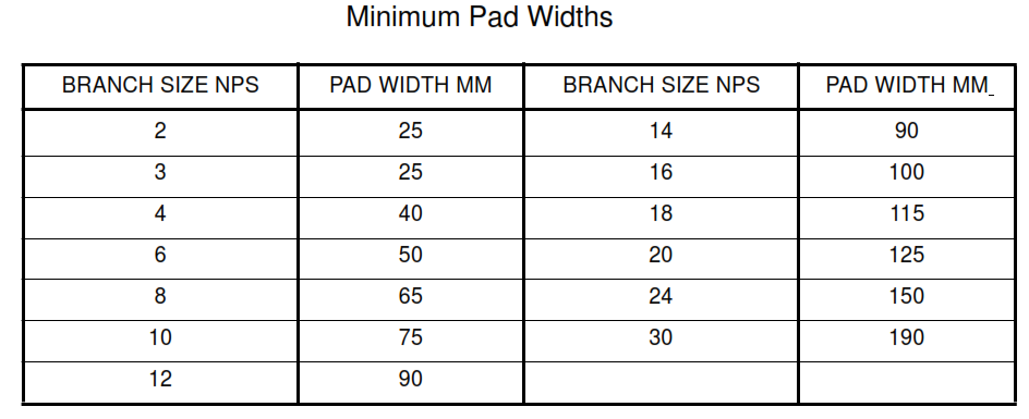
4.10 Minimum Reinforcing Pads
The actual pad width required shall be calculated. The pad thickness shall be no less than the header wall
thickness. Pad thicknesses greater than 1.5 times the nominal header thickness cannot be used to
calculate area replacement or stress concentration factors.
Table I
Minimum Pad Widths