1. SCOPE
……………..
2. REFERENCES
3. DEFINITIONS
4. GENERAL
…………
5. PREPARATION
6. APPROVAL
7. CONTROL
…………
1. Scope
This standard establishes the requirements for the preparation of Safety Instruction Sheets for additions to
existing plants, and for new pipelines or additions to existing pipelines.
2. References
Reference is made in this standard to the following documents. The latest issues, amendments, and
supplements to these documents shall apply unless otherwise indicated.
SABIC Engineering Standard (SES)
SES P01E15 Pressure Testing of Piping System and Lay-up Procedures
American Society Of Mechanical Engineers (ANSI)
B31.3 Chemical Plant and Petroleum Refinery Piping
B31.4 Liquid Transportation Systems for Hydrocarbons, Liquid Petroleum Gas, Anhydrous Ammonia
and Alcohol
B31.8 Gas Transmission and Distribution Piping Systems
3. Definitions
For the purpose of understanding this standard the following definitions apply.
Piping Line List. This document lists the basic design data for each line. The data includes the fluid
symbol, line number, material class, line sizes, description, corrosion allowance, pipewall thickness,
normal operating conditions, maximum upset conditions, design temperature and pressure, minimum test
pressure and type, and insulation requirements.
Safety Data Sheet. This sheet is used to collect the pertinent date for safe engineering and design of
individual lines added to a plant, lines with a change of service, and pipelines.
4. General
4.1 Safety instruction sheets are used to ensure that operating, maintenance and inspection personnel are
made aware of safe operating limits, protective devices and any special safety precautions, as well as
changes, in a consistent format concerning for new and modified piping systems in industrial plants and
pipelines.
4.2 Safety Instruction Sheets shall be prepared for critical plant piping and cross country pipelines. In
addition to critical piping the sheet provides data showing modifications, reuse, and new piping.
5. Preparation
5.1 The following Engineering Forms are available for preparation of Safety Instruction Sheets. Detailed
guidelines listing the key numbers to complete these forms have been prepared.
a. Piping Safety Data Sheet, see Attachment 1, Refer to para. 5.2.
b. Pipeline Safety Data Sheet, see Attachment 2, Refer to para. 5.3.
On each form the required data shall be furnished, as specified, in accordance with the instructions
prescribed in this Standard.
5.2 Form “Piping Safety Data Sheet” is prepared for plant piping which is critical because:
a. Failure leads to a major shutdown of the plant or a major unit in the plant.
b. The design temperature is 425 degrees C (800 degrees F) or higher).
c. The pressure rating is Class 900 pressure rating and higher.
d. Toxic nature of fluid handled.
e. The service has been changed or altered from the original intent.
5.3 Form “Pipeline Safety Data Sheet” shall be prepared and completed for all flowlines, trunklines and
cross country pipelines, in general, carrying any fluid.
6. Approval
The Project Manager is responsible for the preparation and issue of any Safety Data Sheets on new piping
for construction projects. When piping is installed or modified outside a new construction project scope, the
Plant Manager is responsible for Safety Data Sheets preparation.
Copies of the Safety Data Sheets shall be submitted for review and concurrence by the designated
representative(s). The Project Manager will issue revised sheets where necessary as a result of this
review.
7. Control
Pipe and Pipeline Safety Data Sheets shall be assigned suitable numbers and shall become a part of the
project record.
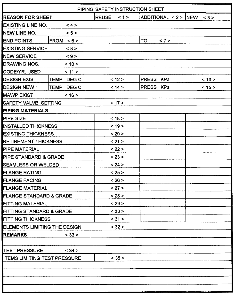
Completion of Piping Safety Instruction Sheet
1, 2, or 3 Mark the reason for the sheet.
4 or 5
Show existing or new line identification, e.g., P-100-6A
6 & 7
Indicate where line starts and ends, e.g., Column C-101 to Pumps G-200 A/B
8 or 9
Give specific data on fluid service; e.g., reduced crude with acid, vapor, etc.
10
Pertinent pipe isometrics, P & ID’s or other reference drawings.
11
Show applicable Industry Code and year, e.g., ANSI B31.3, ’96.
12
Enter the existing design temperature, which would be consistent with the design
condition.
13
Enter the existing design pressure, which would be consistent with the design condition.
14
Enter the new design temperature, which would be consistent with the design condition.
15
Enter the new design pressure, which would be consistent with the design condition.
16
Enter the maximum allowable working pressure (MAWP)
17
Equipment safety valve setting not greater than that shown under key number 13 for
existing or 15 for new.
18
Nominal pipe size.
Note: Extra column has been provided for more than one pipe size entry.
19
Installed pipe wall thickness in millimeters.
20
Existing pipe wall thickness in millimeters.
21
Calculated required minimum wall thickness (Tm). Refer to ANSI B31.3 for method of
calculation.
Note: Tm (Retirement Wall Thickness) Shall Not Be Less Than The Required Wall Thickness For
Mechanical strength. When Tm is for mechanical strength, indicate this in the remarks
section.
22
Pipe material, e.g., carbon steel, stainless steel, etc.
23
Pipe standard and grade, e.g., A-106, Gr.B, API 5L, X-42, etc.
24 Seamless or
welded.
25
Flange rating, e.g., 900#
26
Raised face, ring joint, or flat face.
27
Flange material, e.g., Carbon steel, stainless steel, etc.
28
Flange standard and grade, e.g., A-105, A-350 LF-2, etc.
29
Fitting material, e.g., carbon steel, stainless steel, etc.
30
Fitting standard and grade, e.g., A-105, A-234, WPB, API 5L, Gr. X-42
31
Fitting thickness, i.e., Sch. 40, 3000 lb., etc.
32
Indicate the limiting item, e.g., pipe wall, flanges, process limitations, or any other limiting
article.
33
Any specific remarks regarding material. Include precautions necessary during operation
or tests, such as need to blind off expansion joints during hydro-static tests because they
will not withstand the test pressure.
34
Enter the actual new test pressure. The test pressure should be consistent with the
hydrostatic test diagram and P01E15
35
Show the limiting item of the test pressure, such as flanges, pipe wall thickness, vessel,
exchanger, etc.
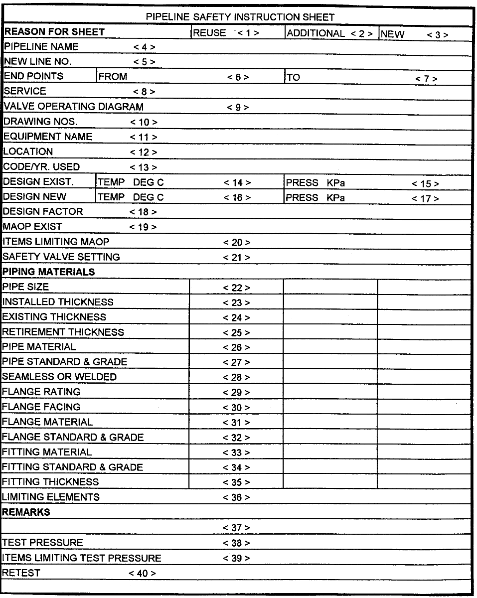
Completion of Pipeline Safety Instruction Sheet
1, 2, or 3 Mark the reason for the sheet.
4
Give the official designation of the line, e.g., “SABIC no. 1”
5
Show new line identification, e.g., P-100-6A
6
Show name of origin, e.g., “Oasis 1”.
7
Show name of termination point, e.g., “Jubail”.
8
Indicate the type of fluid handled, e.g., Arab Light.
9
Show the name of the Valve Operating Diagram of this line, e.g., Jubail no. 1-001. If not
available, give the P & ID drawing number.
10
Pertinent pipe isometrics, P & ID’s or other reference drawings.
11
Provide adequate information to clearly identify the equipment, for example, scraper trap,
block valve MOV-321, etc.
12
Show the location of the equipment by name and kilometer, e.g., Oasis 3 @ Km. 4.5 In
the case of flowlines, testlines, or trunklines, show the trunkline or manifold number.
13
Show applicable Industry Code and year, e.g., ANSI B31.3, ’96.
14
Enter the existing design temperature, which would be consistent with the design
condition.
15
Enter the existing design pressure, which would be consistent with the design condition.
16
Enter the new design temperature, which would be consistent with the design condition.
17
Enter the new design pressure, which would be consistent with the design condition.
18
Show the design factor, and give the basis of the design factor in the remarks area in key
number 37
19
Calculate maximum allowable operating pressure (MAOP) in accordance with applicable
code as limited by flanges or by nominal pipe wall for materials listed under key numbers
22 through 36.
20
Show the item that is limiting the MAOP in key number 19.
21
Show the set pressure of safety valve or sun pressure relief valve or pressure switch or
other safety device if included, and if required for routine operation. Confirm this
information with the P & ID.
22
Nominal pipe size.
Note: Extra column has been provided for more than one pipe size entry.
23
Installed pipe wall thickness in millimeters.
24
Existing pipe wall thickness in millimeters.
25
Calculated required minimum wall thickness (Tm). Refer to the appropriate code for
method of calculation.
NOTE: Tm (retirement wall thickness) shall not be less than the required wall thickness for mechanical
strength. When Tm is for mechanical strength, indicate this in the remarks section.
26
Pipe material, e.g., carbon steel, stainless steel, etc.
27
Pipe standard and grade, e.g., A-106, Gr.B, API 5L, X-42, etc.
28 Seamless or
welded.
29
Flange rating, e.g, Class 1500.
30
Raised face, ring joint, or flat face.
31
Flange material, e.g., Carbon steel, stainless steel, etc.
32
Flange standard and grade, e.g., A-105, A-350, LF-2, etc.
33
Fitting material, e.g., carbon steel, stainless steel, etc.
34
Fitting standard and grade, e.g., A-105, A-234, WPB, API 5L, Gr. X-42
35
Fitting thickness, i.e., Sch. 40, 3000 lb., etc.
36
Indicate the limiting item, e.g., pipe wall, flanges, process limitations, or any other limiting
article.
37
Remarks pertaining to any item or calculation above. Indicate any items or hazards which
require consideration by Operations, Inspection or Maintenance.
38
Enter the actual new test pressure. The test pressure should be consistent with the
hydrostatic test diagram and P01E15
39
Show the limiting item of the test pressure, such as flanges, pipe wall thickness, vessel,
exchanger, etc.
40
Indicate the actual test pressure. The test pressure shall be in accordance with P01E15
and approved by the responsible SABIC Engineering Unit.