1 SCOPE ……………………………………………………………………………………
2 REFERENCES ……………………………………………………………………………………
3 DEFINITIONS ……………………………………………………………………………………
4 GENERAL ……………………………………………………………………………………
5 DESIGN ……………………………………………………………………………………
5.1 General ……………………………………………………………………………………
5.2 Design Conditions ……………………………………………………………………………………
5.3 Pipe ………………………………………………………………………………………………………………..
5.4 Fittings ……………………………………………………………………………………
5.5 Valves ……………………………………………………………………………………
5.6 Flanges ……………………………………………………………………………………
5.7 Gaskets ……………………………………………………………………………………
5.8 Bolts & Nuts ……………………………………………………………………………………
5.9 Branch Connections ……………………………………………………………………………………
6 MATERIALS ……………………………………………………………………………………
6.1 General ……………………………………………………………………………………
6.2 Pipe ………………………………………………………………………………………………………………..
6.3 Fittings ……………………………………………………………………………………
6.4 Valves ……………………………………………………………………………………
6.5 Flanges ……………………………………………………………………………………
6.6 Gaskets ……………………………………………………………………………………
6.7 Bolts & Nuts ……………………………………………………………………………………
7 PIP LINE DESIGNATOR SYSTEM & PIP LINE CLASS INDEX
7.1 PIP Line Designator System ……………………………………………………….
7.2 PIP Line Class Index and Line Class ……………………………………………………….
8 REVISION SUMMARY ……………………………………………………………………………………
Table I Flange contact surface finish ……………………………………………………….
Table II Typical material selection for Pipes ……………………………………………………….
Table III Typical material selection for Wrought Fittings …………………………..
Table IV Typical material selection for Forged Fittings and Flanges …………………………..
Table V Typical Material Selection for Bolts / Nuts …………………………..
1 Scope
1.1 This specification establishes the minimum mandatory requirement for the preparation of Piping
Material Specification.
1.2 This specification stipulates the use of “PIP” (Process Industry Practices) Piping line classes as
the basis for development of Project Piping Material Specification. PIP- line classes are adopted
by SABIC as its corporate Piping Material Specification.
1.3 This specification covers pipes and piping components of new piping systems for use in general
and Petrochemicals plants, whose design is in accordance with ASME B31.3, B31.1, B31.4, or
B31.8 Codes.
2 References
Reference is made in this standard to the following documents. The latest issues, amendments, and
supplements to these documents shall apply unless otherwise indicated.
SABIC Engineering Standards (SES)
P01-E01 Design of Plant piping and Transportation pipelines
P04-S01 Piping Material Specification for Utilities
P15-G01 Selection of Pipe – Options and limitations for design and materials
P18-G01 Design Limitations and Applications of Valves
R10-S01 Instrument Tubing Materials Specification
American Petroleum Institute (API)
941 Steel for Hydrogen service at elevated temperatures and pressures in petroleum Refineries and
petrochemical plants.
American Society for Testing and Materials (ASTM)
A 153 Specification for Zinc coating (Hot-dip) on Iron and Steel Hardware
American Society of Mechanical Engineers (ASME)
B1.1 Unified Inch Screw Threads
B1.20.1 Pipe Threads, General Purpose (Inches)
B16.10 Face-to-Face and End-To-End Dimensions of Valves
B16.11 Forged Fittings, Socket-Welding and Threaded
B16.20 Metallic Gaskets for Pipe Flanges – Ring Joint, Spiral-wound, and Jacketed
B16.21 Non-Metallic Flat Gaskets for Pipe Flanges
B16.25 Buttwelding Ends
B16.28 Wrought Steel Butt Welding Short Radius Elbows and Returns
B16.34 Valves-flanged, Threaded and Welded end
B 16.47 Large diameter steel flanges, NPS 26 through NPS 60
B 16.5 Pipe Flanges and Flanged Fittings NPS 1/2 through NPS 24
B16.9 Factory-Made Wrought Butt Welding Fittings
B18.2.1 Square, Hex, Heavy hex, and Askew head bolts and Hex, Heavy hex, Hex flange, Lobed
head, and Lag screws (inch series)
B18.2.2 Nuts for general applications: Machine screw nuts, Hex, Square, Hex Flange, and coupling
nuts (Inch Series)
B31.1 Power Piping
B31.3 Process Piping
B31.4 Pipe Line Transportation system for liquid hydro carbons and other liquids
B31.8 Gas Transmission and distribution piping systems
B36.10 Welded and Seamless Wrought Steel Pipe.
B36.19 Stainless Steel Pipe
Manufacturers Standardization Society (MSS)
SP-75 Specification for High Test Wrought, Butt-Welding Fittings
SP-83 Class 3000 Steel Pipe Unions, Socket-Welding and Threaded
SP-97 Integrally Reinforced Forged Branch Outlet Fittings — Socket Welding, Threaded, and Butt
welding Ends.
National Association of Corrosion Engineers (NACE)
MR0175/ISO 15156 Petroleum and natural gas Industries-Materials for use in H2S Containing
environments in oil and production-Part 1, Part 2 & Part 3
Process Industry Practices (PIP)
PNCM0001 Piping Line Class Designator System
PNCM0002 Piping Material Specifications- Line Class Index
3 Definitions
For the purpose of understanding this standard, the following definitions apply.
Amine Services: All Amine solutions including MEA (Monoethanolamine), DGA (Diglycolamine).
Caustic Services: All Sodium hydroxide solutions.
Category ‘D’ fluid, Category ‘M’ fluid & High pressure fluid: See definition mentioned in ASME
B31.3
Critical Service: A pipeline service may be classified as critical when its failure could present a hazard
to humans or environment. Pipelines and plant piping in hydrocarbons, hydrocarbon processing, and
firewater service are some examples of critical service.
Hydrogen Service: Process streams containing relatively pure hydrogen and component streams
containing hydrogen with a partial pressure of 350 kPa (absolute) and higher.
PFD: Process Flow Diagram
P&ID: Piping & Instrumentation Diagram
PMS: Piping Material Specifications
Service: Service is related to pressure, temperature, flange rating, special components, and special
requirements of the fluid in a piping system.
Steam Services: All steam and condensate at operating pressures above 100 kPa (1 bar).
4 General
4.1 PIP- line classes are adopted by SABIC as a basis for preparation of Project specific PMS.
4.2 This specification does not cover material specification for Utility Services and shall be as per
SES P04-S01.
4.3 This specification do not cover material specification for Instrument tubing and shall be as per
SES R10-S01.
4.4 The Piping material specification shall be strictly adhered to in the design, requisitioning,
purchasing, fabrication and testing of the piping system.
4.5 Deviations to material of construction/ thickness/ rating etc., that may occur due to changes in
design conditions and /or non-availability. Design Engineering Company shall seek deviation
from SABIC in writing. All such deviations/substitutions shall be duly approved by the SABIC.
5 Design
5.1 General
5.1.1 Seamless pipes and fittings can be supplied in place of welded pipes and fittings (made
out of plates) but with maximum negative tolerance of 0.3 mm of wall thickness.
5.1.2 Category ‘D’ fluid, Category ‘M’ fluid & High pressure fluid as defined in ASME B31.3,
H2 Service, Services requiring PWHT on weld joints, Vacuum service, O2 service and Cryogenic
service shall be clearly marked in Piping line class.
5.1.3 Butt welding ends for Pipes, Fittings, Flanges and Valves shall comply with the
requirements of ASME B16.25.
5.1.4 Piping system (pipes, flanges, fittings, valves and any other components) shall be Buttweld
construction
from
sizes
NPS
½
&above
for the
following.
a. Piping class 900# & above
b. Lines with cyclic services /vibration lines
c. Services lead to crevice corrosion
d. Highly Viscous fluids
e. Any other services as required by Process
5.2 Design Conditions
Design conditions shall be determined in accordance with the applicable ASME B31.3, B31.1,
B31.4 & B31.8 Code and supplemented by SES P01-E01.
5.3 Pipe
5.3.1 Selection of pipes-options and limitation for design and material shall be in accordance
with SES P15-G01.
5.3.2 Pipe dimension shall comply with ASME B36.10 for wrought C.S & A.S steel and for
stainless steel pipe to B36.19 / B36.10. Pipe dimension for non-ferrous and non-metallic pipes
shall comply with respective ASTM Standard.
5.3.3 All pipe threads shall conform to ASME B1.20.1 unless otherwise noted.
5.3.4 Pipe made by acid-Bessemer process shall not be acceptable. Steel pipe shall be made
by open hearth, electric furnace or basic Oxygen process.
5.3.5 The minimum pipe size shall be NPS 1/2 (Nominal Pipe Size) except tubing and piping
used in pump and compressor auxiliary piping, instrument leads, and steam tracing.
5.3.6 Wall thickness :
a. Wall thickness shall be in accordance with the applicable ASME B31.3, B31.1,
B31.4 or B31.8 Code criteria and supplemented by SES P01-E01.
b. Piping component wall thicknesses shall be based on the pressure and temperature
conditions of ASME B16.5 full flange Rating for upto NPS 24. For NPS 26 and
above, wall thickness can be based on the actual design conditions specified. Any
deviation to this requirement shall require SABIC approval. Piping component wall
thicknesses do not include any additional thickness that may be required to
compensate for such design considerations as thermal loads due to restraints, live
loads, hydraulic shock / surge pressures, vehicular loads, and other loads. The
suitability of the specified wall thicknesses for other loads is the responsibility of the
Design Engineer Company.
c. Wall thickness calculations shall be based on the lowest strength component in the
system, considering all factors including the possibility of pipe and fittings having
different maximum allowable stress values, and/or manufacturer’s minus tolerance.
When economics dictates the use of a pipe wall thickness less than that required
for the ASME B16.5 full flange rating, the appropriate design conditions shall be
indicated in the line class for the applicable pipe sizes.
d. Unless otherwise specified, all pressures specified in the PIP individual line classes
are positive pressures. Piping subjected to a negative pressure (vacuum) shall be
investigated on an individual basis.
5.3.7 Non standard pipe sizes NPS 11/4, 21/2, 31/2, 5 and NPS 22 shall not be used except
for connections to equipment or instrument requiring these sizes.
5.3.8 Spiral welded pipes shall not be used in Hydrocarbon services of Process plants.
5.3.9 Welded pipe shall not have more than two longitudinal seam welds for NPS 36 and
above.
5.4 Fittings
5.4.1 Steel butt-welding fittings shall comply with ASME B16.9, unless otherwise specified.
5.4.2 The maximum size of threaded and socket welded joints shall be limited to NPS 1 1/2
and comply with ASME B16.11.
5.4.3 Integrally reinforced outlet fittings (Weldolets, Sockolets, Threadolets etc.) shall comply
with MSS SP-97. Sockolets and Threadolets shall be limited to NPS 1 ½ .
5.4.4 For lateral branch connections, Laterolets shall be used.
5.4.5 Pipe unions shall be forged steel in class 3000 threaded or socket welded shall comply
with MSS SP-83.
5.4.6 Usage of Unions shall be restricted to utility services only.
5.4.7 Use of short radius elbows is subject to the approval of the SABIC and shall comply with
ASME B16.28.
5.4.8 Drain and vent connections on elbows and tees are not allowed.
5.4.9 Miter shall not be used without prior SABIC approval.
5.4.10 Fittings for high pressure gas and oil transmissions and distribution systems (pipelines
fittings) shall comply with MSS-SP-75.
5.4.11 Conical reducers shall not be used.
5.4.12 Use of Non-ASME B16.9 fittings design is subject to SABIC approval and those fittings
shall pass the bursting test specified in ASME B16.9.
5.5 Valves
5.5.1 SABIC adopted PIP’s (Process Industry Practices) Valve material specifications as a
basis for preparation of Project specific Valve Material specification.
5.5.2 Design limitations and applications of Valves shall be in accordance with P18-G01.
5.5.3 Pressure/temperature ratings shall comply with the requirements of ASME B16.34.
5.5.4 Union bonnet, Screwed bonnet and screwed body valves shall not be used in hazardous
or hydrocarbon services.
5.5.5 Pressure seal bonnet shall be used only in valve rating of 900# and above for valve size
NPS 2 onwards, in steam, hydrogen or high-pressure non-corrosive services.
5.5.6 Welded bonnet valves shall be used in hydrogen and steam services for valve size NPS
1 ½ and below . Use of other types of bonnet connections shall require SABIC approval.
5.5.7 Socket weld end valves shall be capable of surviving PWHT, since the application of
heat during PWHT is over the entire valve, and could cause seat and stem mis-alignment.
Otherwise, seats shall be removed during welding, or pipe pups may be used. Socket welding
and threaded end valves requiring seal welding shall have extended bodies or nipples to prevent
damage due to welding heat. As an alternative, flanged valves may be used with approval of
SABIC.
5.5.8 Valve size over NPS 24 for critical valves, welding end valves, and others that cannot be
removed from the line easily, shall be of a type that is repairable on the line (top-entry).
5.5.9 Isolation valves NPS 3 and larger in hydrocarbon service shall not be provided with pure
polymer / elastomer stem packing or stem seals unless they are qualified as fire safe.
5.5.10 Inside screw rising stem (ISRS) and non rising stem valves NPS 2 and smaller shall not
be used in hydrocarbon services. The stem threads could collect corrosion deposits and become
clogged.
5.5.11 Threaded connections on valve bodies and associated piping of Hydrocarbon services
shall be seal welded.
5.5.12 Flangeless (Wafer type) Check valves, Butterfly valves or any other components other
than Spacer & Blinds shall not be used in hydrocarbon and hazardous services.
5.6 Flanges
5.6.1 Flanges shall comply with the following codes, unless otherwise noted.
Up to NPS 24 (150# to 1500# )
ASME B16.5.
Up to NPS 12, 2500#
ASME B16.5
NPS 26 & above (150# to 900# )
ASME B16.47, series B
5.6.2 Fig.8 flanges and Spacer & Blind shall comply with the following codes, unless otherwise
noted.
Up to NPS 24 (150# to 1500#) ASME B16.48
Up to NPS 12 ( 2500# ) ASME B16.48
For other sizes Manufacturer standards / ASME B31.3
Flanges of unlisted materials and flanges not covered by the above standards shall be designed
in accordance with ASME Section VIII Div.1.
5.6.3 Flat face flanges, with full-face gaskets, shall be used when one or both of the mating
flanges in a joint are ASME B16.1. Class 125 gray cast iron, aluminum, or plastic, can be overstressed
by bearing against a raised face. Adapter rings shall be considered to level off the
surface, for mating equipment
5.6.4 In ring joint flanges, thickness of lap remaining after machining the ring groove shall not
be less than the nominal wall thickness of the pipe used. Ring joint flanges for use with
ASME B16.20 ring joint gaskets shall be used for:
a) Flanges in Class 900 and higher ratings
b) Design temperatures in excess of 480 C
c) Hazardous fluid mediums
5.6.5 The hardness of the Ring joint flanges, Blind flanges and Spacers shall have 30 to 50
BHN higher than Ring type gasket hardness value as given in ASME B16.20, to ensure perfect
sealing.
5.6.6 Tongue-and-groove facing, and male-and-female facing joints, shall not be used except
in high-pressure service, when it is necessary to match existing equipment and as per Process
licensor’s recommendation.
5.6.7 Flanges shall be finished in accordance with MSS SP-6, and ASME B46.1. The Table-I
defines the acceptable ranges of contact surface finishes for each type of gasket and service.
The surface finishes are to be specified in Ra, Roughness average, expressed in micro-meters.
For special services such as Vacuum / oxygen, the contact surface finish shall be as per
Licensor’s requirement.
5.6.8 Ring joint flanges shall have flat-bottom type grooves in accordance with ASME B16.20.
5.6.9 Socket weld flanges and socket weld reducing flanges shall be used for NPS 1 ½ &
below.
5.6.10 Slip-on flanges and reducing slip-on flanges shall be limited to Category-D fluid service
only. However, slip-on flanges shall not be used in the following services:
a. Severe cyclic conditions. See ASME B31.3
b. Design temperatures above 230 C, or where the corrosion allowance exceeds 3
mm
c. ASME B16.5 Class 300 or higher rating
d. Flange sizes larger than NPS 24, unless stress calculations in accordance with
ASME Section VIII Div 1, Appendix 2, with thermal and other external piping loads
considered, show that the slip-on flanged joint will not be over-stressed
e. Piping subjected to vibrations
f. Hydrogen services
5.6.11 Lap joint flanges shall not be used for severe cyclic conditions, High temperature, Low
temperature and Cryogenic service applications.
5.6.12 Weld neck flanges shall be used in piping line classes for services such as steam,
process hydrocarbon and corrosive services.
5.7 Gaskets
5.7.1 Non metallic gaskets shall comply with ASME B16.21 (corresponding to ASME B16.5
flanges) up to NPS 24 and B16.21 (corresponding to ASME B16.47 Series B flanges) beyond
NPS 24, unless otherwise specified.
5.7.2 Spiral would gaskets (SP.WND or SPWD), corrugated gaskets and Ring Joint Gaskets
shall comply with ASME B16.20.
5.7.3 The Gasket selected shall be in accordance with the following criteria:
a) Spiral wound Gasket shall be adopted in all piping line classes up to 600 class
rating in process hydrocarbons, corrosive and steam services.
b) Flat ring gasket may be used only in category-D fluid services.
c) Full face gaskets, shall be used when one or both of the mating flanges made of
Gray cast iron, Aluminum, FRP or Plastic.
d) Ring Joint gasket (Octagonal) shall be adopted in all piping line classes having
rating 900 rating and above, for design temperatures in excess of 480 C and for
Hazardous fluid mediums.
5.7.4 Centering ring: All Spiral wound gaskets shall be furnished with centering ring. The
centering is carbon steel as a standard, which is painted, metal plated or otherwise coated to
inhibit atmospheric corrosion. The thickness of centering ring shall be as per ASME B 16.20. For
cold service use a stainless steel ring.
5.7.5 Inner rings: Inner rings keep the windings from extruding into the pipe. The material of
inner ring shall be stainless steel unless otherwise specified. Inner ring is required in the
following sizes / material /services
a. NPS 26 and larger sizes for ASME pressure Classes 150 and 300
b. NPS 14 and larger sizes for ASME pressure Class 600 and 900
c. NPS 12 and larger sizes for ASME pressure Class 1500.
d. Cryogenic services of temperature -45 ºC to -196 ºC
e. High Temperature service s of temperature above 427 ºC
f. For all PTFE filler gaskets
g. Polymer fluid service
h. Highly erosive services
5.7.6 Flat face flanges, with full face gaskets shall be used when one or both of the mating
flanges in a joint are ASME B16.1. Class 125 gray cast iron, aluminum, or plastic, may be overstressed
by
bearing
against a
raised
face
5.7.7 Hardness of metallic ring joint gasket shall not exceed the values as specified in ASME
B 16.20.
5.7.8 Compressed sheet gaskets are 1.6 mm thick ring type.
5.7.9 The thickness of spiral winding is generally 4.5 mm without compression. The
compressed thickness of gasket 3.2 mm shall be considered.
5.7.10 Gaskets shall be suitable for the intended service and compatible with the flange facing,
the strength of the flange, and bolting. Use no more than one gasket between mating surfaces.
5.7.11 When using spiral wound gaskets, the gasket contact area of the flange shall not be
coated, to ensure proper contact surface for sealing purpose.
5.8 Bolts & Nuts
5.8.1 Stud bolts shall only be used for Process piping, unless otherwise specified.
5.8.2 Dimensions and tolerances for bolts shall be in accordance with ASME
B 18.2.1 and nuts to be B18.2.2. Reference shall also be made to ASME B16.5 for machine
bolts, studs bolts and nuts.
5.8.3 Threads shall be smooth and may be machined, ground, or rolled. Threading shall be in
accordance with ASME B1.1, Class 2A for bolts, and Class 2B for nuts. The coarse thread
series for sizes 1 inch & smaller and the 8 pitch (8UN) thread series for sizes above 1 inch shall
be used.
5.8.4 Nuts for Machine bolts and Studs bolts shall be Heavy hexagon series.
5.8.5 Flat washers under the nuts are required for special cases only, such as on insulating
flanges and under the nuts bearing against plastic flanges.
5.8.6 Belleville washers may be required for severe cyclic service, and bolt service
temperatures above 450 ºC.
5.8.7 Jackscrews shall be used to facilitate flange separation for maintenance. Joint
assemblies that often require frequent separation include orifice plates, spectacle plates,
spacers, screens, and dropout spools.
5.8.8 When flange separators are used, the use of jackscrews shall be optional.
5.8.9 For orifice flanges, jackscrews shall be installed at 3 and 9 o’clock positions.
5.9 Branch Connections
5.9.1 Branch connections shall be in accordance with Branch table provided at the end of the
individual line classes of PIP- PMS.
5.9.2 For rating 900# and above ‘Pipe to Pipe branches’ or ‘Pipe to Pipe with reinforcement’
shall not be used. Use only Tees or Weldolets.
6 Materials
6.1 General
6.1.1 Selection of steels for pipes and piping components exposed to hydrogen service shall
be in accordance with API 941.
6.1.2 Irrespective of the material code requirement, all welded pipes and fittings used in
cryogenic (below -45 ºC) and low temperature application (up to -45 ºC) shall meet impact test
requirements of ASME B31.3. The impact test temperature shall be -196 ºC for stainless steel
and -45 ºC for Low temperature carbon steel.
6.1.3 Materials for use in H2S Containing environments in oil and production shall comply with
NACE MR-0175/ISO15156; those services shall be considered as NACE service.
6.1.4 Iron pipes (cast, ductile / malleable) and piping components shall not be used in
Hydrocarbon services of Process plants.
6.1.5 Pipes and piping components including Bolts/ Nuts made of Austenitic stainless steels
shall be furnished in the solution annealed condition.
6.1.6 The use of any piping materials containing asbestos is prohibited.
6.1.7 Materials covered by this specification include pipe, valves, fittings, flanges, other
common piping components and specialties. Individually engineered items (which require data
sheets) are covered in other specifications, or by a written description on the design drawings.
The following are some examples of individually engineered items.
a. Spring hangers
b. Expansion joints
c. Eye washers & Safety showers
d. Steam traps
e. Strainers
6.2 Pipe
6.2.1 Selection of pipes-options and limitation for design and material shall be in accordance
with P15-G01.
6.2.2 Material selection and size range for seamless and welded pipes for typical services,
See Table-II.
6.2.3 Electric resistance welded (ERW) and spiral welded carbon steel pipe shall not be used
for hazardous services.
6.2.4 Furnace butt welded pipe shall not be used.
6.2.5 Only steel pipe specifications shall be used to handle flammable fluids.
6.2.6 Carbon steel pipe for hazardous service shall have specified minimum yield strength
(SMYS) of not less than 35 Ksi (241 MPa).
6.2.7 Specify post weld heat treatment (PWHT) when required by the applicable code. In
general, all caustic soda solutions, Monoethanol amine solutions and NACE services require
PWHT at all temperatures. In addition, certain amines require PWHT above 90 C if
concentrated, and above 60 C if diluted.
6.3 Fittings
6.3.1 Material selection and size range for seamless and welded wrought fittings for typical
services, See Table-III.
6.3.2 Material selection for forged fittings for typical services, See Table-IV.
6.3.3 All welded fittings shall be 100 percent Radiographed.
6.4 Valves
6.4.1 Design limitations and applications of steel Gate, Ball, Globe, and Check valves shall be
in accordance with P18-G01.
6.5 Flanges
6.5.1 Material selection of Forged flanges for typical services, See Table- IV
6.5.2 Blind flanges shall be of the same material as the weldnecks, in all services. In corrosive
atmospheres, stainless steel Blind flanges shall be used. For larger size blinds C.S with S.S
cladding shall be considered.
6.6 Gaskets
6.6.1 The gasket material shall be compatible for the intended service.
6.6.2 Spiral wound gasket material shall be SS304 / SS316 stainless steel winding, flexible
graphite filler, in most services, including process hydrocarbon and steam. The centering is
carbon steel as a standard, which is painted, metal plated or otherwise coated to inhibit
atmospheric corrosion.
6.6.3 When gaskets operate in temperatures below minus 45 ºC, centering ring and inner ring
shall be Stainless steel grade 304 materials. Filler materials that retain flexibility at low
temperature such as Teflon (PTFE) shall be compatible to service temperature/process fluid.
6.6.4 Spiral wound gaskets for acid without chlorides shall be Alloy 20 stainless steel winding
and PTFE filler with stainless steel inner rings.
6.6.5 Spiral wound gaskets for acid with chlorides shall be Hastelloy windings with PTFE filler.
6.6.6 Spiral wound gaskets for caustic service shall be Monel windings with PTFE filler.
6.7 Bolts & Nuts
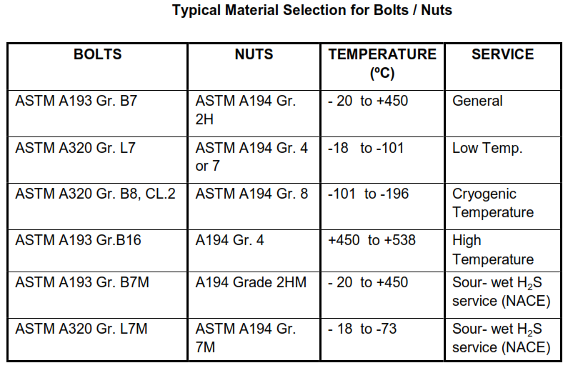
6.7.1 Material for process and general services shall be as per Table-V. The material selection
for other cases must be approved by SABIC.
6.7.2 All bolts and nuts shall be galvanized or cadmium coated for protection against corrosive
and sea water environments.
6.7.3 The following may be required for underground piping:
a. Corrosion resistant alloys
b. Painting of exposed portions of the bolts and sealing the gap between flange faces.
7 PIP Line Designator System & PIP Line Class Index
7.1 PIP Line Designator System
PIP Line class designator shall provide a uniform system for identifying piping line classes.
SABIC adopted to utilize PIP Line class designator system and Design Engineering Company
shall comply with PIP PNCM0001.
7.2 PIP Line Class Index and Line Class
PIP PNCM0002 provides listing of the PIP Piping Material Specifications (PMS). This line class
index contains pressure class, primary materials, corrosion allowance, service type, and joint
constructions. For each Line class PIP has detailed specifications including Valve Material
Specifications. Design Engineering Company to choose equivalent /nearly equivalent Line class
and prepare project specific PMS based on service conditions (Fluids type, Base material,
Design pressure / design temperature, Corrosion allowance, etc.).
Table I
Flange contact surface finish
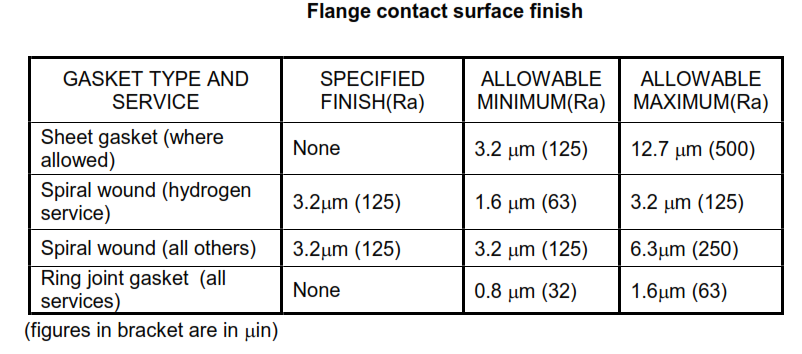
Table II
Typical material selection for Pipes

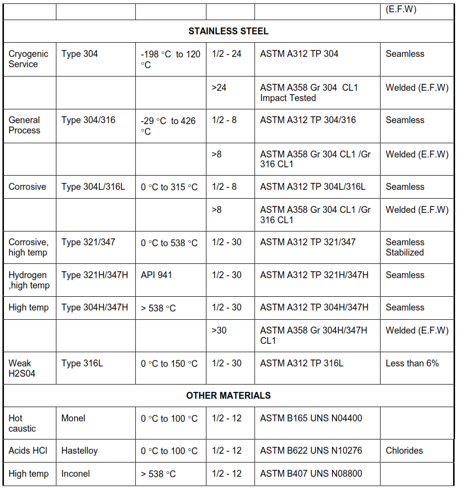
Table III
Typical material selection for Wrought Fittings
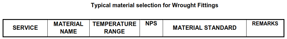
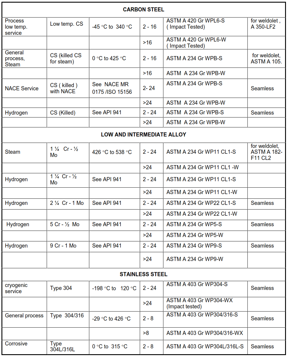
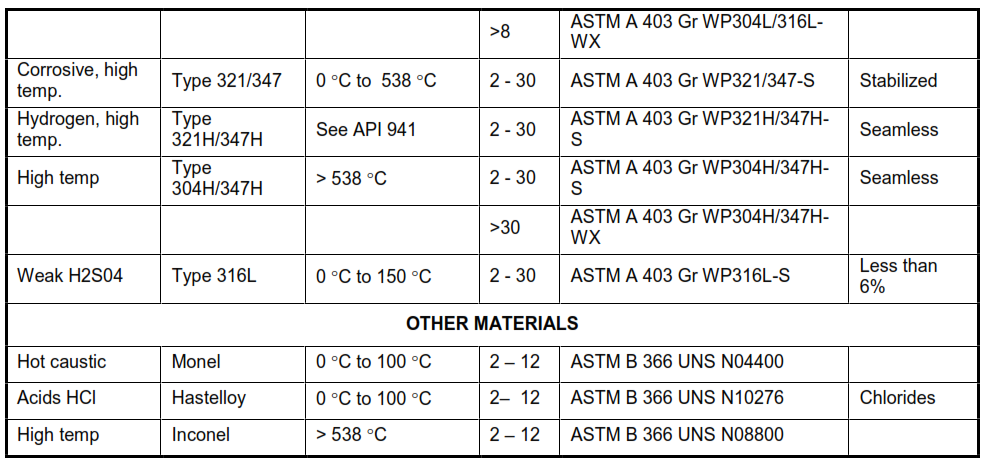
Table IV
Typical material selection for Forged Fittings and Flanges

Table V
Typical Material Selection for Bolts / Nuts