1. SCOPE …………………………….2. REFERENCES
3. GENERAL REQUIREMENTS
TABLE
I
Connectors and Color Coding
1. Scope
This standard supplements ASME B31.3 and ASME B31.1 codes and defines additional requirements
governing the design of plant utility stations for water (potable and raw), steam, compressed air, and inert
gases.
This standard does not apply to specific type of valve connections required for bottled gases (oxygen,
nitrogen, chlorine, acetylene, refrigerants, ammonia, propane and butane).
2. References
The selection of material and equipment, and the design, construction, maintenance, and repair of
equipment and facilities covered by this standard shall comply with the latest edition of the references listed
below, unless otherwise noted.
Industry Codes and Standards
SABIC Engineering Standards
P01-E19 Utility Piping System, Connections to Process Equipment, Safety Shower and Eyewash
American Society of Mechanical Engineers
ASME B31.1 Power Piping
ASME B31.3 Chemical Plant and Petroleum Refinery Piping
3. General Requirements
3.1 The design of utility Stations located in various plants within one plant area shall be uniform and shall be
such that the risk of accidental connection to the wrong utility is minimum. See SES P01-E19 for limitations
on connections.
3.2 The connectors and color coding in Table I shall be standardized for utility stations in new plants not
governed by paragraph 4.1.
Ta ble I
Connectors and Color Coding
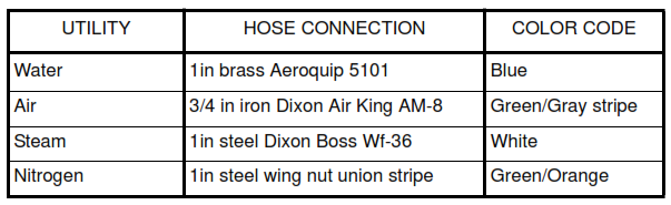
Items specified by brand names or proprietary names are not intended to exclude equivalent items offered
by other manufacturers.
3.3 Hose connections, where applicable, shall be positioned approximately 1.2m above finished plant
grade or above platform of multilevel equipment, pointing 45 degrees downward. The piping shall be
securely bolted to a supporting structure.
3.4 Each utility take-off connection shall be located at the top of the horizontal main header or auxiliary
header. Root valves shall be provided for each utility take-off connection from a main header or auxiliary
header whcich cannot be taken out of service without shutting down a complete processing unit or
operating facility. Root valves are not required for each utility take-off from a utility header which can be
isolated without interrupting the normal operation of a unit.
Instrument air take-off connections shall alway be provided with root valves.
3.5 Each utility line shall be provided with an isolation valve just upstream of the specified hose connector
(see paragraph 4.2) at the termination. Ball valves shall be used for air, water, and nitrogen services, globe
or angle valves shall be used for steam service. Each line shall have a service name plate in Arabic and
English indicating the service. The utility pipe and the ends of hoses provided with the station shall be color
coded.
3.6 The steam line shall have a steam trap and shall be insulated for personnel protection except for utility
steam take-off lines. Utility steam take-off lines shall be insulated but shall not be provided with steam traps.
Utility steam stations located above the utility steam header shall be self-draining towards the utility steam
header. Utility steam lines to utility stations below the utility steam header shall be allowed to gather steam
condensate, which is removed by operations before applying the utility steam.