This article is about PLC Applications Examples And Solutions. Read Also Previous Articles if you did not read before.
- Lecture 1: What is Programmable Logic Controller in PLC?
- Lecture 2: PLC Hardware Components – PC Information
- Lecture 3: PLC Internal Architecture and Diagram Explanation
- Lecture 4: What is PLC System? and Working Principle
- Lecture 5: How to Connect Input Devices to PLC? Input Devices Examples
- Lecture 6: How to Connect Output Devices to PLC? PLC Output Devices
PLC Applications Examples
In the control system examples given, let’s further explore the operation of a conveyor belt and a lift.
1. Conveyor Belt Control System:
The purpose of this control system is to transport goods from a loading machine to a packaging area using a conveyor belt. The control system consists of the following components:
- Input Devices: Contact Switches
- Contact switch 1: Indicates when an item is loaded onto the conveyor belt.
- Contact switch 2: Activates when the item reaches the far end of the conveyor and falls into the packaging area.
- Output Device: Conveyor Motor
- The motor starts running when contact switch 1 is activated, indicating an item is on the belt.
- The motor stops when contact switch 2 is activated, indicating the item has reached the packaging area.
The control sequence can be summarized as follows:
- When contact switch 1 detects an item on the conveyor belt, it sends a signal to the PLC.
- The PLC activates the conveyor motor, which starts running and moves the item along the belt.
- The motor continues running until contact switch 2 is triggered by the item falling into the packaging area.
- Contact switch 2 sends a signal to the PLC, which then stops the conveyor motor.
- The motor remains off until contact switch 1 detects the next item on the belt.
2. Lift Control System:
The control system is designed for a simple goods lift that moves items between different levels. The control system consists of the following components:
- Input Devices: Push Button Switches and Limit Switches
- Push button switches:
- Ground level upward button: Pressed to send the lift upward from the ground level.
- Upper level upward button: Pressed to request the lift to move upward from the upper level.
- Upper level downward button: Pressed to send the lift downward from the upper level.
- Lower level downward button: Pressed to request the lift to move downward from the lower level.
- Limit switches:
- Access gate limit switch: Indicates whether the access gate to the lift platform is closed or not.
- Push button switches:
- Output Device: Lift Motor
- The motor moves the lift upward or downward based on the control signals from the PLC.
The control sequence can be summarized as follows:
- If the access gate limit switch indicates that the access gate is closed:
If the ground level upward button or the upper level upward button is pressed, the PLC activates the lift motor to move the lift upward.
If the upper level downward button or the lower level downward button is pressed, the PLC activates the lift motor to move the lift downward.
The lift motor continues running until the desired level is reached or until another command is received.
The lift motor stops when the desired level is reached, and the motor remains off until a new command is initiated and the access gate is confirmed to be closed.
These examples demonstrate how input devices (such as switches and sensors) provide signals to a PLC, which then controls output devices (such as motors) based on the input signals to achieve the desired system operation.
In the provided text, two additional control system examples are described: a Robot Control System and a Liquid-Level Monitoring system. Additionally, a mention is made of Packages on Conveyor Belt Systems. Let’s explore these examples in more detail:
3. Robot Control System:
The control system for a robot, as shown in Figure 2.41, utilizes directional control valves to control the various movements of the robot. The system consists of the following components:
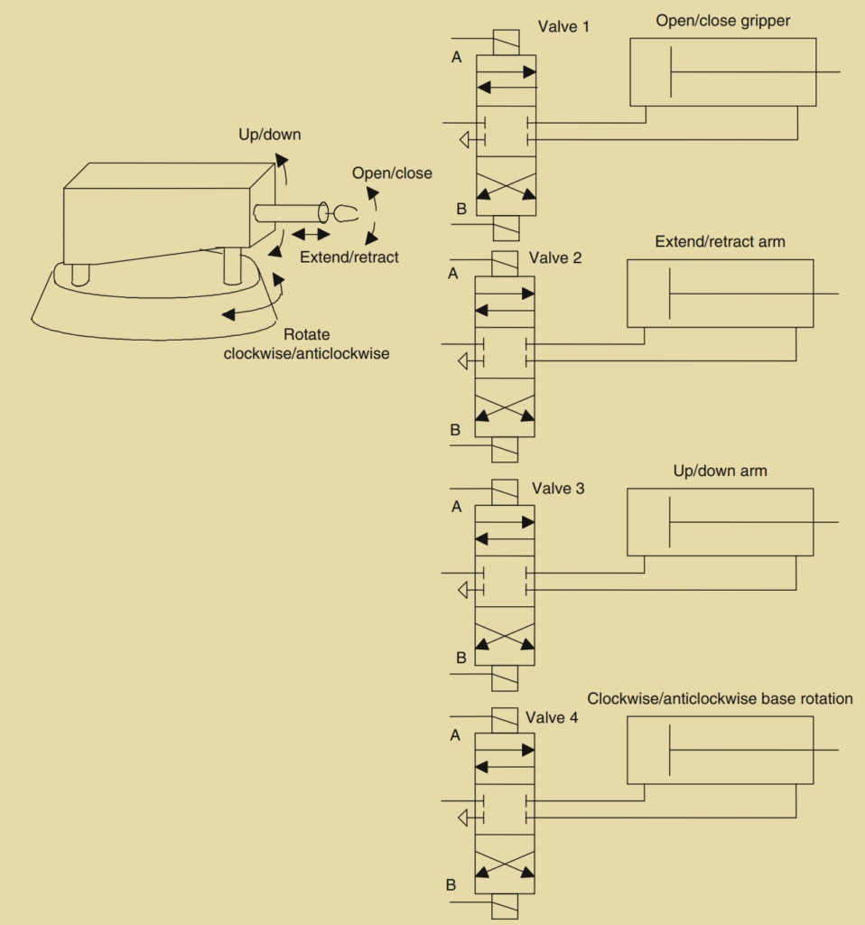
- Directional Control Valves:
- Valve 1: Controls the gripper of the robot.
- Valve 2: Controls the extension and retraction of the robot arm.
- Valve 3: Controls the upward and downward movement of the arm.
- Valve 4: Controls the rotation of the robot base in clockwise or anticlockwise direction.
- Solenoids:
- Solenoid A: Energizing this solenoid of Valve 1 causes the gripper to close.
- Solenoid B: Energizing this solenoid of Valve 1 causes the gripper to open.
- Solenoids of Valve 2: Control the extension and retraction of the robot arm.
- Solenoids of Valve 3: Control the upward and downward movement of the arm.
- Solenoids of Valve 4: Control the rotation of the robot base.
The control sequence can be summarized as follows:
- To close the gripper, Solenoid A of Valve 1 is energized, causing the gripper to move to the right.
- To open the gripper, Solenoid B of Valve 1 is energized, causing the gripper to move to the left.
- The arm extension and retraction, upward and downward movement, as well as base rotation, are controlled by energizing the corresponding solenoids of the respective valves.
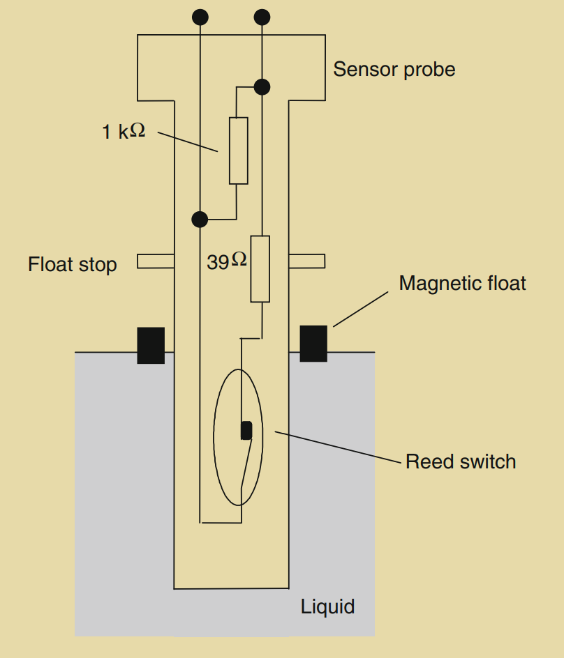
4. Liquid-Level Monitoring System:
The liquid-level monitoring system, as depicted in Figure 2.42, is designed to provide an on/off signal when the liquid in a container reaches a critical level. The system includes the following components:
- Magnetic Float: Attached to a ring, which falls as the liquid level decreases.
- Sensor Probe: Detects the position of the magnetic float.
- Reed Switch: Positioned to open or close based on the level of the magnetic float.
- Resistors: A 39 Ω resistor and a 1 kΩ resistor are connected in parallel, and their effective resistance changes based on the state of the reed switch.
The control sequence can be summarized as follows:
- As the liquid level falls, the magnetic float attached to the ring also falls.
- When the critical level is reached, the magnetic float opens the reed switch, causing a change in resistance from approximately 37 Ω (39 Ω resistor) to 1 kΩ (1 kΩ resistor).
- The change in resistance can be detected and used for signal conditioning to provide suitable on/off signals indicating the liquid level.
5. Packages on Conveyor Belt Systems:
In certain scenarios, it is necessary to detect the presence of nontransparent items on a conveyor belt at a specific position. This can be achieved using a light emitter on one side of the belt and a photoelectric sensor on the other side. The process is as follows:
- A light emitter is positioned on one side of the conveyor belt.
- A photoelectric sensor is positioned on the opposite side of the belt.
- When a nontransparent item passes between the light emitter and the photoelectric sensor, it interrupts the light beam, indicating the presence of the item at the desired position.
- In the case of transparent items like bottles, the photoelectric sensor can be positioned to detect reflected light, allowing the system to determine when the item is in the required.
Summary:
Follow is summary which is highlighting the distinction between sensors and transducers, and it describes common terms used to specify the performance of sensors. It also mentions various commonly used sensors and output devices. Let’s review the information:
Sensors and Transducers:
- Sensor: An input device that provides a usable output in response to a specified input.
- Transducer: A device that converts a signal from one form to a different physical form.
Performance Specifications of Sensors:
- Accuracy: The extent to which the value indicated by a measurement system or element might be wrong.
- Error: The difference between the result of a measurement and the true value.
- Nonlinearity Error: The error that occurs when assuming a linear relationship between input and output.
- Hysteresis Error: The difference in output for the same measured quantity depending on whether the value was reached by a continuously increasing or decreasing change.
- Range: The limits within which an input can vary.
- Response Time: The time it takes for the output to reach a specified percentage of the steady-state value after an abrupt increase in input from zero to a constant value.
- Sensitivity: Indicates how much the output changes when the measured quantity changes by a given amount.
- Stability: The system’s ability to give the same output for a given input over time.
- Repeatability: The system’s ability to provide the same value for repeated measurements of the same quantity.
- Reliability: The probability that a system will operate up to an agreed level of performance.
Commonly Used Sensors:
- Mechanical Switches
- Proximity Switches: Eddy current, Reed, Capacitive, or Inductive types
- Photoelectric Sensors: Transmissive or Reflective types
- Encoders: Provide a digital output based on angular or linear displacement. Incremental encoders measure angular displacement, while absolute encoders give a binary output defining each angular position uniquely.
- Temperature Sensors: Bimetallic strips, Resistive Temperature Detectors (RTDs), Thermistors, Thermodiodes, Thermotransistors, or Thermocouples.
- Position and Displacement Sensors: Potentiometers, LVDTs (Linear Variable Differential Transformers), and Capacitive Displacement Sensors.
- Strain Gauges: Provide a resistance change when strained.
- Pressure Sensors: Diaphragm gauges.
- Liquid-Level Detectors: Pressure gauges or floats.
- Fluid Flow Meters: Orifice flow meters.
Commonly Used Output Devices:
- Relays
- Directional Control Valves with Cylinders
- DC Motors
- Stepper Motors
These devices are commonly employed in control systems to convert input signals into usable outputs and perform various control functions.