This article is about PLC Output Devices and How to Connect Output Devices to PLC? Read Also Previous Articles if you did not read before.
- Lecture 1: What is Programmable Logic Controller in PLC?
- Lecture 2: PLC Hardware Components – PC Information
- Lecture 3: PLC Internal Architecture and Diagram Explanation
- Lecture 4: What is PLC System? and Working Principle
- Lecture 5: How to Connect Input Devices to PLC? Input Devices Examples
PLC Output Devices
The output ports of a PLC can be connected to different types of devices such as relays, optoisolators with transistors, or triacs. These devices are used to switch other devices on or off based on the digital signals from the PLC.
An actuator is a device that takes the electrical signal from the PLC and converts it into a physical action to control a process. Here are a few examples of actuators commonly used with PLCs:
- Electric Motors: Electric motors are used to drive machinery and equipment. They can be controlled by the PLC to start, stop, and regulate their speed and direction of rotation.
- Solenoid Valves: Solenoid valves are used to control the flow of liquids or gases in a system. The PLC can activate or deactivate solenoid valves to control the flow of fluids and the operation of pneumatic systems.
- Hydraulic and Pneumatic Cylinders: These cylinders use hydraulic or pneumatic pressure to generate linear or rotary motion. The PLC can control the activation and movement of these cylinders to perform tasks such as lifting, pushing, or rotating objects.
- Heating and Cooling Elements: The PLC can control heating elements, such as electric heaters, or cooling elements, such as fans or refrigeration units, to regulate the temperature in a system or process.
- Indicator Lights and Alarms: Output channels of the PLC can be connected to indicator lights or audible alarms to provide visual or audible feedback on the status or condition of the system.
These are just a few examples, and there are many other types of actuators that can be used depending on the specific application and process requirements.
1. Relay
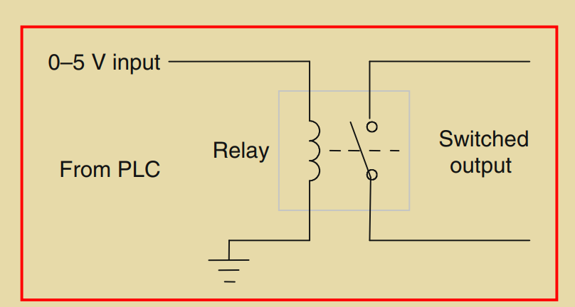
A relay is an electrical device that uses a solenoid to control a switch. When a current passes through the solenoid, it creates a magnetic field that attracts nearby ferrous metal components. In a relay, this magnetic attraction is utilized to operate a switch. Relays are commonly used to control larger currents or voltages and to isolate the control circuitry from the power being switched.
In the context of a relay connected to the output of a PLC, when the PLC output switches on, it activates the solenoid, creating a magnetic field that pulls on the relay contacts and closes the switch(es). This allows the relay to handle much larger currents. For example, a relay can be used to switch on the current to a motor.
Relays can have multiple sets of contacts, which are referred to as poles. The contacts can be normally open (NO) or normally closed (NC) when there is no input. When selecting a relay for a specific application, factors such as the required number of poles, initial contact conditions, rated voltage, and current need to be considered.
A latching relay is a type of relay that maintains its open or closed state even after the power is removed from the solenoid. This can be useful in situations where it’s necessary to keep the switch in a specific position.
The term contactor is used to describe a relay specifically designed to handle large currents from high-voltage sources. Contactors are commonly used in industrial applications to control motors, lighting systems, and other heavy-duty electrical loads.
2. Directional Control Valves
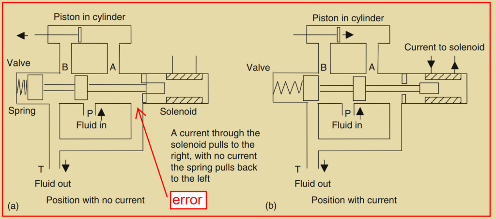
Another example of a solenoid actuator is a solenoid-operated valve, which is used to control the direction of flow of pressurized air or oil. These valves are commonly used to operate other devices, such as a piston in a cylinder. One type of solenoid-operated valve is a spool valve, which controls the movement of a piston in a cylinder.
In a spool valve, pressurized air or hydraulic fluid enters through a port (P) from a pump or compressor, and another port (T) is used for fluid return to the supply tank or venting air to the atmosphere in the case of a pneumatic system. When no current is passing through the solenoid, the fluid is directed to the right side of the piston, causing it to move to the left. When current is passed through the solenoid, the spool valve switches the fluid to the left side of the piston, causing it to move to the right. This movement of the piston can be utilized to perform various actions, such as pushing a deflector to divert items on a conveyor belt or generating any other type of powered displacement.
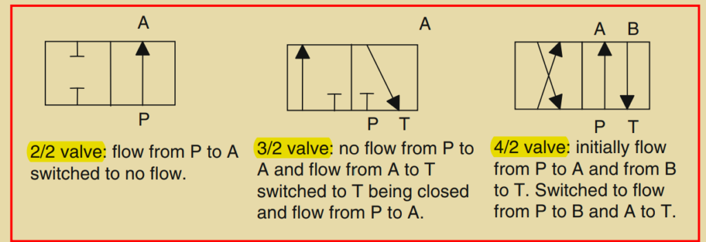
Directional control valves are classified based on the number of ports and control positions they have. In the example shown in Figure 2.25, the valve has four ports (A, B, P, and T) and two control positions. Therefore, it is referred to as a 4/2 valve. The standard symbol used to represent valves in drawings is a square, with each square representing a control position. In the case of the valve shown in Figure 2.25, the symbol consists of two squares. Within each square, arrows indicate the flow direction, or a terminated line indicates no flow path. This helps to illustrate the switching positions of the valve.

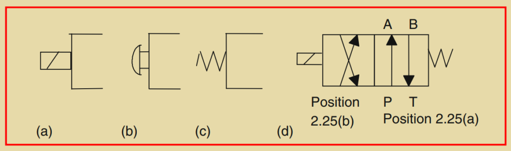
In diagrams representing valves, the pipe connections, or inlet and output ports, are indicated by lines drawn outside the box. These lines are only drawn for the box representing the unactuated or rest position of the valve. This can be seen in Figure 2.26c, which shows the pipe connections for the valve shown in Figure 2.25. Figure 2.27 provides more examples of directional valves and their switching positions.
To indicate the actuation methods used with valves, additional symbols are added to the valve symbol in diagrams. Figure 2.28 shows examples of these symbols. For the valve shown in Figure 2.25, which has a spring for one position and a solenoid for the other position, the symbol would be represented as shown in Figure 2.28d.
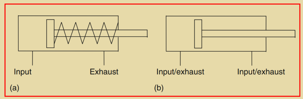
Directional valves are often used to control the motion of pistons in cylinders, where the displacement of the pistons performs the desired actions. A single-acting cylinder (Figure 2.29a) is powered by pressurized fluid applied to one side of the piston, causing motion in one direction. The motion in the opposite direction is typically achieved by a return mechanism, such as an internal spring. On the other hand, a double-acting cylinder (Figure 2.29b) is powered by fluid for motion in both directions of the piston.
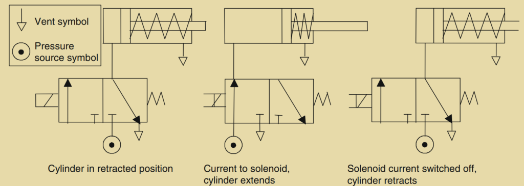
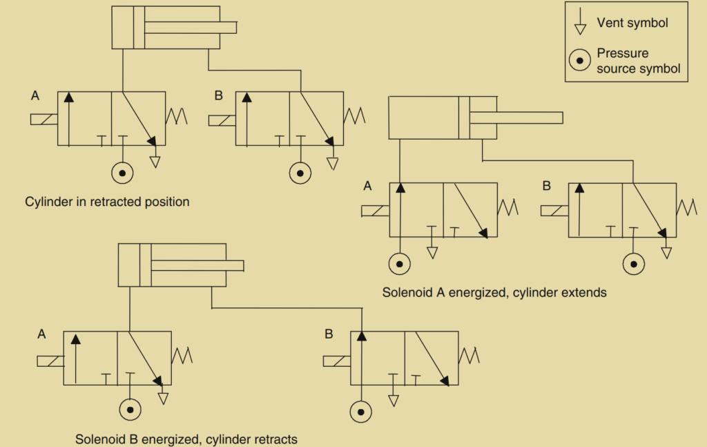
Figure 2.30 demonstrates how a valve can be used to control the direction of motion of a piston in a single-acting cylinder, while Figure 2.31 illustrates how two valves can be used to control the action of a piston in a double-acting cylinder.
3. Motors
A DC motor consists of coils of wire mounted on the armature, which is a cylinder made of ferromagnetic material. The armature is mounted on bearings and can freely rotate. The motor operates within a magnetic field generated by permanent magnets or current passing through field coils. When a current flows through the armature coil, it experiences forces that cause it to rotate. To maintain continuous rotation, brushes and a commutator are used to reverse the current through the coil every half rotation.
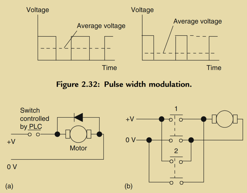
The speed of rotation of a DC motor can be controlled by adjusting the current flowing through the armature coil. Since fixed voltage supplies are commonly used to power the motor, the desired variable current is achieved through electronic circuitry. This circuitry can control the average voltage and, consequently, the current by modulating the width of the voltage pulses applied to the armature. This technique, known as pulse width modulation (PWM), allows a PLC to control the motor’s speed by manipulating the width of the voltage pulses.
In some cases, an industrial process may only require the PLC to switch a DC motor on or off. This can be accomplished using a relay, as shown in Figure 2.33a. The diode in the circuit serves to dissipate the induced current caused by the back electromotive force (EMF) generated by the motor.
If the PLC needs to change the direction of rotation of the motor, relays can be used to reverse the current flow in the armature coil. This enables the motor to rotate in the opposite direction.
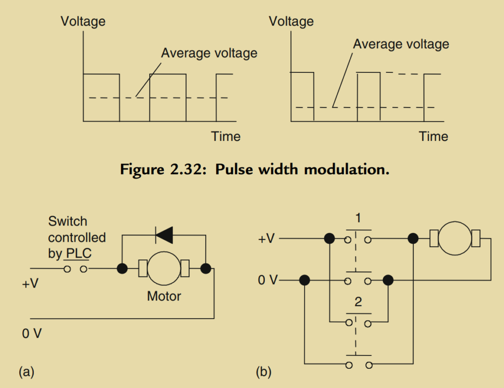
Figure 2.33b illustrates the basic principle for controlling the direction of rotation in a DC motor. To achieve rotation in one direction, switch 1 is closed while switch 2 is opened. Conversely, for rotation in the opposite direction, switch 1 is opened and switch 2 is closed.
Another type of DC motor is the brushless DC motor. In this motor, a permanent magnet generates the magnetic field, and instead of the armature coil rotating, the magnet itself rotates within a stationary coil. Unlike conventional DC motors, brushless DC motors do not require a commutator to reverse the current in the coil for each half rotation. Instead, electronic circuitry is used to control the current direction.
Brushless DC motors can be started and stopped by manipulating the current to the stationary coil. However, reversing the motor’s direction is more challenging because the electronic circuitry used for commutation does not easily allow for current reversal. To address this, sensors are often incorporated into the motor to detect the positions of the north and south poles. By precisely timing the switching of current to the coils based on these sensor readings, the forces applied to the magnet can be reversed, resulting in a change in the motor’s direction.
The speed of rotation in a brushless DC motor can be controlled using pulse width modulation (PWM). By adjusting the average value of the constant DC voltage pulses, the motor’s speed can be regulated.
Although AC motors are generally cheaper, more durable, and more reliable than DC motors, maintaining constant speed and controlling it can be more complex with AC motors. As a result, DC motors, particularly brushless permanent magnet motors, are widely preferred for control applications.
4. Stepper Motors
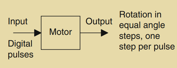
Stepper motors, also known as stepping motors, are motors that rotate in equal angles or steps in response to digital pulses supplied to their inputs. For example, if one input pulse corresponds to a rotation of 1.8 degrees, then 20 pulses would result in a rotation of 36 degrees. To achieve a complete revolution of 360 degrees, 200 pulses would be required. Stepper motors are commonly used for precise angular positioning.
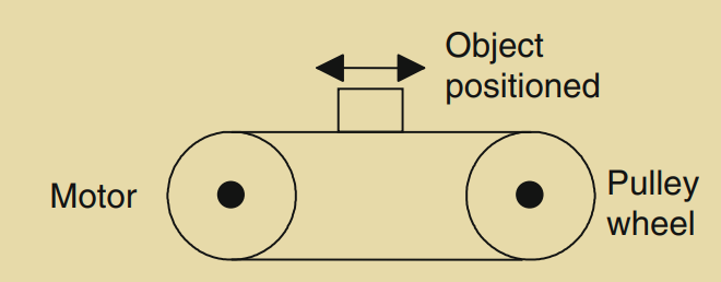
When a stepper motor is employed to drive a continuous belt, it can be utilized for accurate linear positioning. This type of motor is used in various applications such as computer printers, robots, machine tools, and instruments that require precise positioning.
There are two main types of stepper motors: permanent magnet and variable reluctance. The permanent magnet type features a rotor with a permanent magnet, while the variable reluctance type incorporates a soft steel rotor. Additionally, there is a hybrid version that combines both permanent magnet and variable reluctance characteristics. The permanent magnet type is the most commonly used.
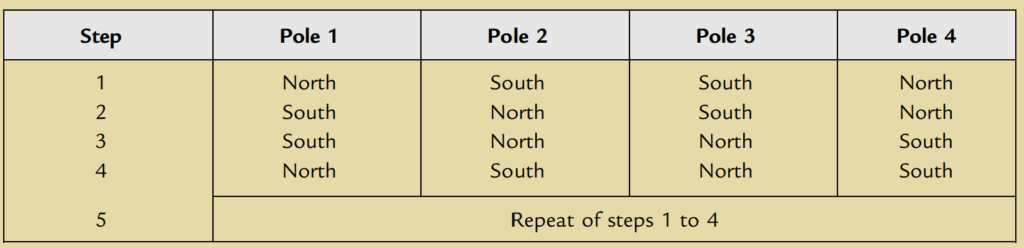
In the permanent magnet stepper motor, depicted in Figure 2.36, there are two pairs of stator poles. Each pole is activated by passing a current through the corresponding field winding. The winding coils are designed in such a way that opposite poles are created on opposite coils. The current is supplied to the windings from a DC source through switches. By switching the currents through the coils to produce the specific pole configuration shown in Figure 2.36, the rotor will move and align itself with the next pair of poles, coming to a stop. This movement corresponds to a rotation of 90 degrees. If the current is then switched to reverse the polarities, the rotor will move another step to align with the subsequent pair of poles at an angle of 180 degrees, and so on. The polarities associated with each step follow a specific pattern.
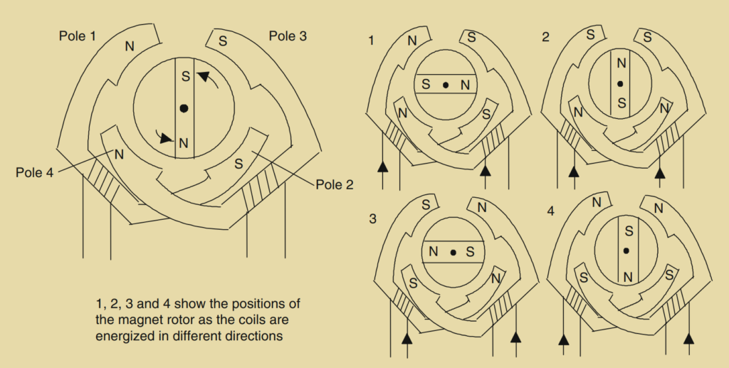
Thus in this case there are four possible rotor positions: 0°, 90°, 180°, and 270°.
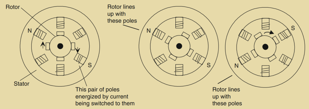
In the variable reluctance type of stepper motor, as shown in Figure 2.37, the rotor is made of soft steel and has a certain number of teeth, which is typically fewer than the number of poles on the stator. The stator consists of pairs of poles, and each pair can be activated by passing a current through the coils wound around it, creating an electromagnet. When a pair of poles is activated, a magnetic field is generated, attracting the nearest pair of rotor teeth to align with the poles. This alignment represents the position of minimum reluctance. By subsequently switching the current to the next pair of poles, the rotor can be made to rotate and align with the new set of poles. By sequentially switching the current between pairs of poles, the rotor can rotate in steps.
Another type of stepper motor is the hybrid stepper motor, which combines features of both the permanent magnet and variable reluctance motors. Hybrid steppers have a rotor with a permanent magnet encased in iron caps that are designed with teeth. The rotor aligns itself in the position of minimum reluctance when a pair of stator coils is energized.
When specifying stepper motors, several terms are commonly used:
- Phase: This refers to the number of independent windings on the stator. Two-phase motors are typically used in light-duty applications, three-phase motors are often variable reluctance steppers, and four-phase motors are commonly employed in higher-power applications.
When working with stepper motors, there are several important terms to understand:
- Step angle: The step angle refers to the angle through which the rotor rotates for each switching change of the stator coils. It is typically expressed in degrees, and it determines the angular resolution of the motor.
- Holding torque: Holding torque is the maximum torque that can be applied to a powered stepper motor without causing it to move from its rest position or lose steps. It represents the motor’s ability to hold a position when under load.
- Pull-in torque: Pull-in torque is the maximum torque required for a stepper motor to start rotating and reach synchronism without losing any steps. It indicates the motor’s ability to initiate motion.
- Pull-out torque: Pull-out torque is the maximum torque that can be applied to a stepper motor while it is running at a given stepping rate without losing synchronism or missing steps.
- Pull-in rate: The pull-in rate is the maximum switching rate or pulse rate at which a loaded stepper motor can start rotating without losing steps. It determines the motor’s responsiveness to changes in input signals.
- Pull-out rate: The pull-out rate is the switching rate at which a loaded stepper motor can remain in synchronism as the switching rate is reduced. It indicates the motor’s ability to maintain accurate positioning at different speeds.
- Slew range: The slew range is the range of switching rates between the pull-in rate and the pull-out rate within which the motor can run in synchronism but cannot start or reverse its motion.
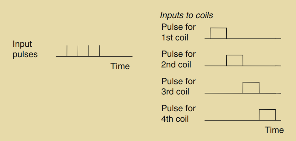
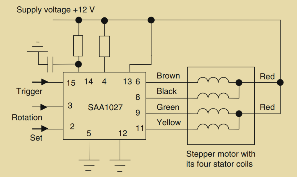
To drive a stepper motor and make it rotate step by step, the stator coils must be switched on and off in the correct sequence in response to a sequence of input pulses. Driver circuits are used to generate the required sequencing. For example, the SAA 1027 is a driver circuit commonly used for four-phase unipolar stepper motors. The input pulses can be supplied by a microprocessor or another control system.
It’s worth noting that stepper motors can be categorized as unipolar or bipolar based on the wiring configuration. Unipolar motors allow current to flow in only one direction through each motor terminal, while bipolar motors allow current to flow in either direction through each terminal.