This article is about Input Devices Examples and How to Connect Input Devices to PLC? Read Also Previous Articles.
- Lecture 1: What is Programmable Logic Controller in PLC?
- Lecture 2: PLC Hardware Components – PC Information
- Lecture 3: PLC Internal Architecture and Diagram Explanation
- Lecture 4: What is PLC System? and Working Principle
PLC Input Output Devices
Input and output devices play a crucial role in the interaction between a programmable logic controller (PLC) and the external world. Here is a brief overview of typical input and output devices used with PLCs:
Input Devices:
- Digital Input Devices: These include mechanical switches (such as limit switches, push buttons), proximity switches (inductive, capacitive, or photoelectric), and encoders (rotary or linear) that provide on/off or binary signals to the PLC.
- Analog Input Devices: These devices provide continuous or analog signals to the PLC. Examples include temperature and pressure switches, potentiometers, linear variable differential transformers (LVDTs), strain gauges, thermistors, thermotransistors, and thermocouples.
Output Devices:
- Relays: Relay outputs are commonly used in PLC systems to control external devices. They provide electrical isolation between the PLC and the controlled equipment.
- Contactors: Contactors are heavy-duty electrical switches used to control high-power loads, such as motors or large lighting systems.
- Solenoid Valves: Solenoid valves are electromechanical devices used to control the flow of fluids (liquids or gases) in pneumatic or hydraulic systems.
- Motors: PLCs can control various types of motors, including AC motors and DC motors, for driving mechanical equipment or machinery.
These are just some examples of the input and output devices used with PLCs. The specific choice of devices depends on the requirements of the application, such as the nature of the process being controlled and the types of signals or actions required.
It’s worth noting that modern PLCs often provide built-in digital and analog input/output (I/O) modules that are designed to directly interface with various types of input and output devices. These modules typically offer signal conditioning, isolation, and protection features, simplifying the connection and integration of devices into the PLC system.
PLC Input Devices
Input devices used with programmable logic controllers (PLCs) include sensors and transducers that provide signals to the PLC based on a specified physical input. Here are some key terms and considerations related to input devices:
Sensor and Transducer:
- Sensor: An input device that provides a usable output in response to a specific physical input. For example, a thermocouple converts temperature differences into electrical outputs.
- Transducer: A device that converts a signal from one form to a different physical form. While sensors are often transducers, other devices like motors can also be transducers.
Digital and Analog Sensors:
- Digital Sensors: These sensors provide on/off or discrete outputs that can be easily connected to PLC input ports. Examples include mechanical switches, proximity switches, and encoders.
- Analog Sensors: These sensors provide continuous or analog signals that need to be converted to digital signals before being input to PLC ports. Examples include temperature and pressure switches, potentiometers, LVDTs, strain gauges, thermistors, thermotransistors, and thermocouples.

Performance Specifications:
- Accuracy: The extent to which a measurement system or element might deviate from the true value. Nonlinearity and hysteresis errors are examples of inaccuracies.
- Range: The limits within which the inputs of a sensor can vary. It defines the minimum and maximum values the sensor can measure.
- Response Time: The time taken for a sensor’s output to settle to a specified percentage of the steady-state value after a change in input. Rise time and settling time are specific types of response time.
- Sensitivity: The ratio of output change to input change for a given sensor. It indicates how much the output changes when the measured variable changes by a certain amount.
- Stability and Drift: Stability refers to the ability of a sensor to give the same output over time, while drift describes changes in output over time. Zero drift refers to changes in output when there is zero input.
- Repeatability: The ability of a measurement system to give the same value for repeated measurements of the same variable. It is affected by random fluctuations in the environment.
- Reliability: The probability that a measurement system or element will operate to an agreed level of performance for a specified period, subject to specified environmental conditions.
These specifications provide valuable information about the performance and limitations of sensors, aiding in their selection and use in PLC applications.
As an illustration of the use of these terms in specification, the following were included in the specification of a MX100AP pressure sensor (see later in this chapter, Section 2.1.8, for an explanation of this sensor):
Supply voltage: 3 V (6 V max)
Supply current: 6 mA
Full-scale span: 60 mV
Range: 0 to 100 kPa
Sensitivity: 0.6 mV/kPa
Nonlinearity error: ±0.05% of full range
Temperature hysteresis: ±0.5% of full scale
Input resistance: 400 to 550 O
Response time: 1 ms (10% to 90%)
The following are examples of some of the commonly used PLC input devices and their sensors.
1. Mechanical Switches
Mechanical switches are commonly used as input devices with PLCs. They generate on/off signals based on a mechanical input that opens or closes the switch. Here are some key points regarding mechanical switches:
Switch Operation:
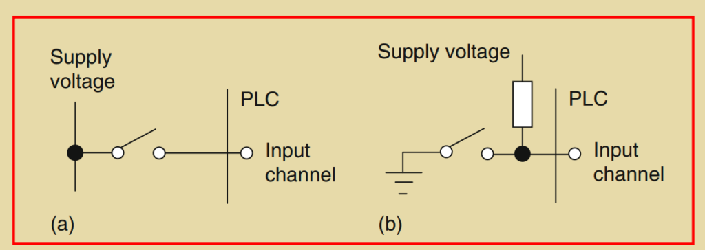
- Workpiece Detection: Mechanical switches can be used to detect the presence or absence of a workpiece or object. When the workpiece presses against the switch, it closes, indicating the presence of the workpiece. The switch is open when the workpiece is absent.
- Logic Levels: The switch generates logic level signals that correspond to the workpiece presence or absence. For example, a closed switch may represent a logic level of 1, while an open switch may represent a logic level of 0. The voltage levels associated with the logic levels can vary based on the PLC system.
Normally Open (NO) and Normally Closed (NC):
- Switch Contacts: Mechanical switches can have normally open (NO) or normally closed (NC) contacts. An NO switch has open contacts in the absence of a mechanical input, and the input is used to close the switch. An NC switch has closed contacts in the absence of a mechanical input, and the input is used to open the switch.
- Configuration: Some switches can be configured as either NO or NC by selecting the appropriate contacts.
Number of Poles and Throws:
- Poles: Mechanical switches are specified in terms of the number of poles, which refers to the number of separate circuits that can be completed by the same switching action.
- Throws: The throws indicate the number of individual contacts available for each pole.
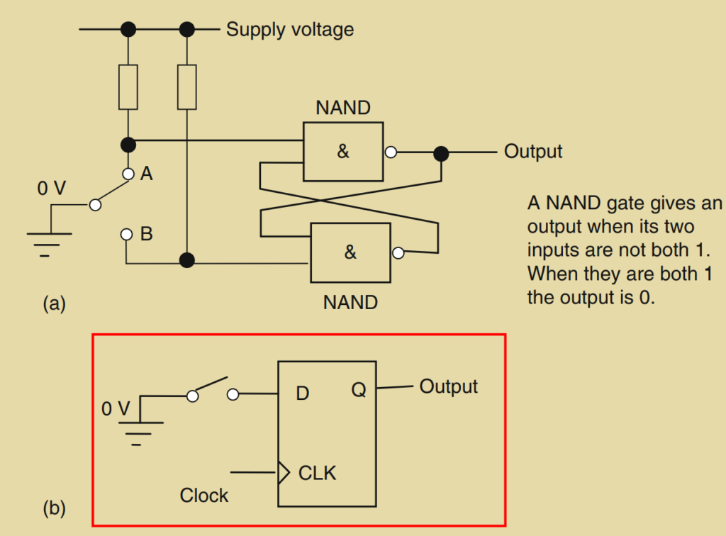
Switch Bounce:
- Bounce Phenomenon: When a mechanical switch is closed or opened, bounce can occur, causing the contacts to make or break inconsistently. The contacts can bounce back and forth like an oscillating spring, leading to multiple signals instead of a single clean transition.
- Eliminating Bounce: To eliminate spurious signals caused by bounce, various techniques can be employed. These may include software delays in the PLC program or the use of debounce circuits. NAND gates or D flip-flops can be used to debounce the switch signals.
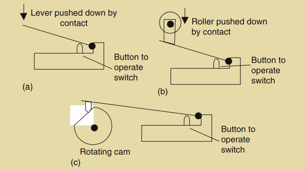
Limit Switches:
- Function: Limit switches are used to detect the presence or passage of a moving part. They can be actuated by cams, rollers, or levers. For example, a rotating cam can turn the switch on and off during specific time intervals.
Liquid-Level Switches:
- Function: Liquid-level switches are used to control the level of liquids in tanks. They typically consist of vertical floats that move with the liquid level, activating switch contacts to indicate the level.
Mechanical switches offer a simple and reliable means of input for PLC systems, and their characteristics and configurations can be adapted to suit specific application requirements.
debounce an SPST switch.
2. Proximity Switches
Proximity switches are used to detect the presence of an object without the need for physical contact. They offer a non-intrusive and reliable means of sensing in various applications. Here are the key points about different types of proximity switches:
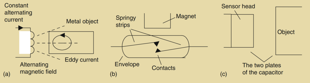
Eddy Current Proximity Switch:
- Operation: This type of proximity switch utilizes a coil that is energized by a constant alternating current, generating a magnetic field.
- Detection: When a metallic object approaches the switch, eddy currents are induced in the object. These eddy currents create a magnetic field that, in turn, induces an EMF (electromotive force) back in the coil.
- Voltage Change: The voltage amplitude required to maintain the constant coil current changes due to the induced EMF, providing a measure of the proximity of metallic objects.
- Electronic Switch Circuit: The voltage change can be used to activate an electronic switch circuit, typically a transistor, which switches its output from low to high, creating an on/off device.
- Detection Range: The detection range for such objects is typically around 0.5 to 20 mm.
Reed Switch:
- Construction: A reed switch consists of two overlapping, but not touching, strips of a springy ferromagnetic material enclosed in a glass or plastic envelope.
- Operation: When a magnet or current-carrying coil is brought close to the switch, the magnetic field magnetizes the strips, causing them to attract and make contact, closing the switch.
- Applications: Reed switches are commonly used in burglar alarms to detect the opening of doors or windows. The magnet is placed in the moving part (e.g., the door), and the reed switch is positioned in the frame.
Capacitive Proximity Switch:
- Principle: Capacitive proximity switches operate based on changes in capacitance.
- Capacitance and Proximity: The capacitance of a pair of plates separated by a distance depends on the separation. By using one plate as the sensor and the other as the object or the surrounding environment, changes in proximity can be detected by measuring capacitance changes.
- Metallic and Non-metallic Objects: Capacitive proximity switches can detect both metallic and non-metallic objects, as capacitance is influenced by the dielectric properties of the material.
- Sensing Range: The typical sensing range for capacitive proximity switches is around 4 mm to 60 mm, depending on the specific sensor.
- Applications: These switches are often used in applications such as detecting the presence of objects on conveyor belts, determining liquid levels, or even detecting the presence of materials inside containers.
Inductive Proximity Switch:
- Design: Inductive proximity switches consist of a coil wound around a ferrous metallic core.
- Inductance Change: When a ferrous metal object approaches the switch, the amount of metallic core associated with the coil changes, resulting in a change in inductance.
- Resonant Circuit: The change in inductance can be monitored using a resonant circuit, and the resulting current variation can be used to activate an electronic switch circuit.
- Detection Range: Inductive proximity switches typically have a detection range of around 2 mm to 15 mm.
- Applications: These switches are often used to detect the presence of metal caps on bottles moving along a conveyor belt.
Proximity switches offer versatility in detecting the presence of objects, whether metallic or non-metallic, and find widespread use in automation, manufacturing, security systems, and other industries. The selection of a proximity switch depends on the specific application requirements, including the type of objects to be detected, the desired sensing range, and environmental conditions.
3. Photoelectric Sensors and Switches
Photoelectric sensors and switches are widely used in automation and industrial applications for object detection. They work by utilizing light beams to detect the presence or absence of objects. Here are the key points about photoelectric sensors and switches:
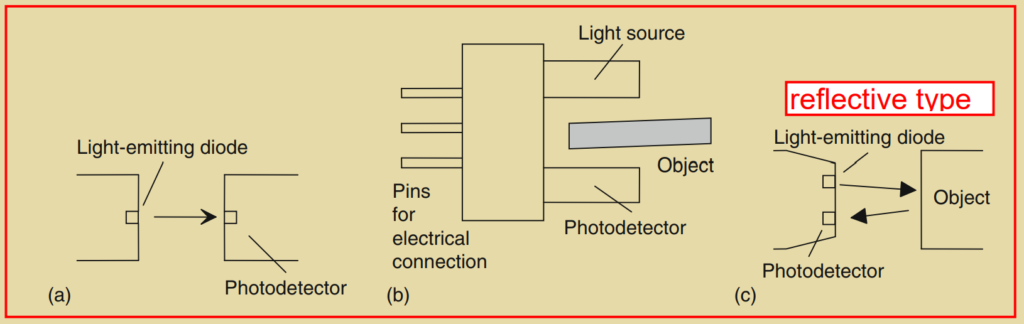
Transmissive Photoelectric Sensors:
- Operation: In transmissive sensors, an emitter (typically an infrared LED) emits a beam of light, and a detector (often a phototransistor or photodiode) is positioned opposite to detect the light.
- Object Detection: When the object being detected breaks the light beam, the light is interrupted, and the detector registers the absence of light.
- Applications: Transmissive sensors are commonly used in applications such as counting parts on conveyor belts or detecting objects passing through a specific point.
Reflective Photoelectric Sensors:
- Operation: Reflective sensors use a similar setup with an emitter and a detector, but they position them next to each other. The light emitted by the emitter reflects off the object and is detected by the detector.
- Object Detection: The presence of an object is detected when the reflected light reaches the detector.
- Applications: Reflective sensors are often used to detect the presence of transparent liquids in containers or to detect the position of objects using reflective surfaces.
Radiation Emitter and Detector:
- Emitter: The emitter is typically an LED that emits infrared radiation. It provides the light source for the sensor.
- Detector: The detector can be a phototransistor, photodiode, or photoconductive cell, depending on the specific sensor design. Phototransistors and photodiodes convert light into electrical signals, while photoconductive cells change resistance based on light intensity.
Output and Signal Processing:
- Output: The output of the sensor can be configured to switch either to a high or low state when light strikes the detector, indicating the presence or absence of an object.
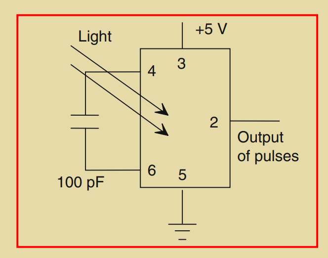
- Signal Processing: If the sensor output needs to measure light intensity, amplification and signal conversion may be required. This can be done using an analog-to-digital converter (ADC) to convert the analog signal to a digital format. Alternatively, a light-to-frequency converter can be used to convert light intensity to a frequency of pulses.
- Integrated Circuit Sensors: Integrated circuit sensors combine the light sensor and signal processing circuitry into a single package. These sensors, such as the Texas Instrument TSL220, incorporate the light sensor and voltage-to-frequency converter, simplifying the interface and providing digital output.
Photoelectric sensors and switches offer advantages such as non-contact detection, high speed, and long sensing ranges. They are widely used in various industries, including manufacturing, packaging, and automation, for applications such as object detection, counting, sorting, and presence sensing. The choice of the sensor type depends on the specific application requirements, object characteristics, and environmental conditions.
4. Encoders
Encoders are devices used to measure angular or linear displacement and provide digital output. There are two main types of encoders: incremental encoders and absolute encoders. Here are the key points about encoders:
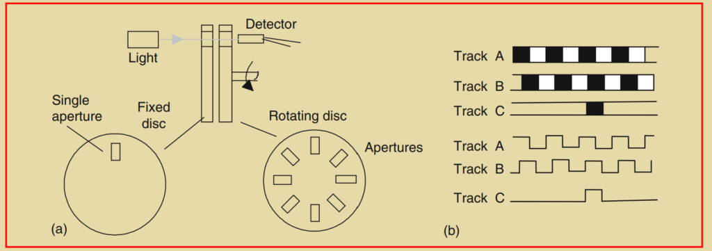
Incremental Encoders:
- Operation: An incremental encoder detects changes in displacement from a reference position. It consists of a rotating disc with slots and a light sensor. As the disc rotates, the slots alternately transmit and block a light beam, generating pulsed outputs from the sensor.
- Resolution: The number of pulses produced is proportional to the angle or distance traveled, and the resolution depends on the number of slots on the disc. Higher slot count increases the resolution.
- Direction Detection: Basic incremental encoders with one track cannot determine the direction of rotation. To address this, encoders often have multiple tracks, usually two or three, with different phase offsets. The phase difference between the tracks helps determine the direction of rotation.
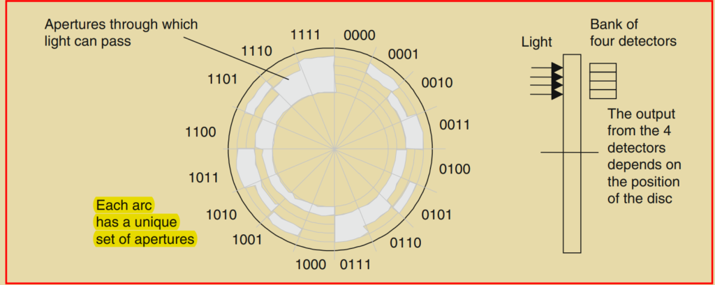
Absolute Encoders:
- Operation: An absolute encoder provides the actual angular or linear position without requiring a reference point. It uses a pattern of slots or marks on a rotating disc to uniquely define each position. Sensors detect the pattern and convert it into a binary code representing the position.
- Resolution: The resolution of an absolute encoder depends on the number of tracks or bits in the binary code. More tracks or bits allow for a greater number of positions to be detected and result in higher resolution.
- Multiple Tracks: Absolute encoders often have multiple concentric tracks with slots or marks. Each track corresponds to a specific bit in the binary code, and the combination of the outputs from all tracks determines the absolute position.
Resolution and Accuracy:
- Resolution: The resolution of an encoder is the smallest increment of displacement that can be detected. It is determined by the number of slots, marks, or tracks on the encoder disc.
- Accuracy: The accuracy of an encoder refers to how closely it measures the actual position. It depends on factors such as the precision of the disc manufacturing, sensor accuracy, and signal processing.
Applications
- Encoders are used in various applications that require precise position sensing and control, such as robotics, CNC machines, motor control systems, and automated measurement devices.
- Incremental encoders are commonly used for speed and distance measurement, while absolute encoders are suitable for applications that require precise position information.
Encoders play a crucial role in providing position feedback and enabling precise control in many industrial and automation systems. The choice between incremental and absolute encoders depends on the specific application requirements, including the needed resolution, accuracy, and the ability to determine the direction of movement.

In practice, the Gray code is often used in absolute encoders instead of the normal binary code. The Gray code is a modified binary code where only one bit changes between consecutive numbers. This code is preferred in absolute encoders because it minimizes errors that may occur during transitions between adjacent positions.
The advantage of the Gray code is that it reduces the possibility of errors due to multiple bits changing simultaneously, which can occur in normal binary codes. By having only one bit change at a time, the Gray code ensures that the transition from one position to the next involves the minimum number of bit changes, reducing the likelihood of misinterpretation or errors.
However, many systems and applications are designed to work with standard binary code. In such cases, a circuit or logic circuitry is required to convert the Gray code output of an absolute encoder into the corresponding binary code that the system can understand. This conversion circuitry ensures compatibility between the encoder’s Gray code output and the binary-based systems that receive and process the encoder data.
By using a Gray-to-binary code converter circuit, the converted binary code can be used by systems that are designed to work with binary data, allowing for seamless integration and utilization of the encoder’s position information.
5. Temperature Sensors
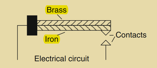
Bimetal elements are simple temperature sensors that provide an on/off signal when a specific temperature is reached. They consist of two strips of different metals bonded together, such as brass and iron, which have different coefficients of expansion.
When the temperature of the bimetal strip increases, the metals expand at different rates, causing the strip to curve. The metal with higher expansion is on the outside of the curve. As the strip cools, the bending effect is reversed. This bending movement can be utilized to make or break electrical contacts, generating an on/off current in an electrical circuit at a particular temperature.
While bimetal elements are not highly accurate, they are commonly used in domestic central heating thermostats due to their simplicity and robustness. They provide a cost-effective solution for temperature control in various applications where precise temperature measurement is not required.
The resistive temperature detector (RTD) is another type of temperature sensor. It utilizes the property of electrical resistance in metals or semiconductors that changes with temperature. In the case of RTDs, metals like platinum, nickel, or nickel alloys are commonly used.
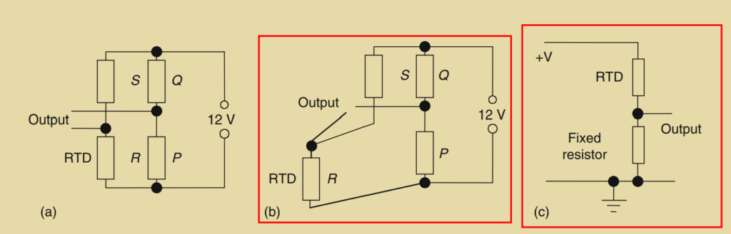
RTDs can be incorporated as one arm of a Wheatstone bridge circuit to measure temperature (Figure 2.12a). The Wheatstone bridge is balanced when the resistors in the bridge arms are arranged such that P/Q = R/S. Any deviation from this balanced condition due to a change in resistance results in an output voltage. The resistance of an RTD varies linearly with temperature over a wide range, although the actual change in resistance per degree is relatively small.
One challenge with resistance thermometers is the presence of long leads connecting them to the bridge, which have their own resistance that can change with temperature. To overcome this issue, a three-wire circuit configuration (Figure 2.12b) is often used. This configuration compensates for changes in lead resistance by affecting two arms of the bridge, balancing out the effects.
Resistance thermometers, such as RTDs, are known for their stability and accuracy, but they can be relatively expensive. They are available in the form of wire-wound elements housed inside ceramic tubes or as thin film elements deposited on a suitable substrate. These sensors are commonly used in industrial and scientific applications where precise temperature measurements are required.
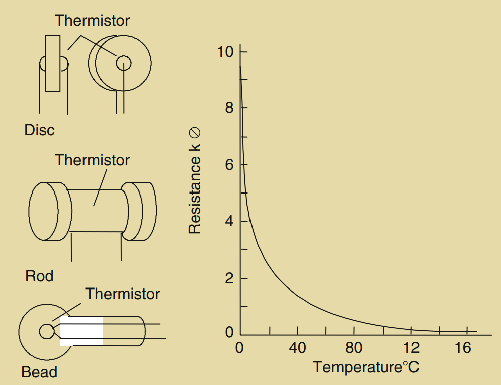
Semiconductors, particularly thermistors, exhibit significant changes in resistance with temperature. However, the relationship between resistance and temperature is nonlinear for thermistors. There are two types of thermistors commonly specified based on their temperature coefficient of resistance (TCR):
- Negative Temperature Coefficient (NTC) thermistors: These thermistors have a negative TCR, meaning that their resistance decreases as the temperature increases.
- Positive Temperature Coefficient (PTC) thermistors: These thermistors have a positive TCR, resulting in an increase in resistance with an increase in temperature.
While thermistors can be used in a Wheatstone bridge configuration, they are more commonly employed in potential divider circuits (Figure 2.12c). In this setup, the changing resistance of the thermistor affects the voltage drop across a fixed resistor, allowing the voltage to be used as an analog signal representing the temperature.
Thermistors offer several advantages, including their affordability, compact size, and rapid response to temperature changes. They exhibit a wide range of resistance variation with temperature. However, their nonlinearity poses a challenge for accurate temperature measurement, and their usable temperature range is often limited compared to other temperature sensors. Despite these limitations, thermistors find widespread use in various applications where cost-effectiveness and responsiveness are prioritized over absolute accuracy.
Thermodiodes and thermotransistors are semiconductor devices that utilize the temperature-dependent diffusion of electrons and holes across a junction to measure temperature. These devices can be integrated into circuits to provide an output voltage that is proportional to the temperature being measured.
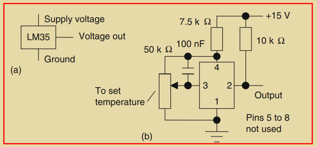
One widely used integrated circuit for temperature sensing is the LM35. It is a precision temperature sensor that provides an output voltage of 10 mV per degree Celsius when a positive supply voltage of +5V is applied. The output voltage can be directly interfaced with analog systems for temperature measurement.
By using the analog output of a temperature sensor like the LM35, it is possible to create a digital temperature switch by employing a comparator amplifier. The analog output is compared with a set value, and the comparator produces a logic 1 signal when the temperature voltage input is equal to or greater than the set point, and a logic 0 signal otherwise. This allows for on/off temperature control based on a specific temperature threshold.
Integrated circuits like the LM3911N combine a thermotransistor temperature-sensitive element with an operational amplifier. When the operational amplifier is configured as a comparator, the output of the chip switches as the temperature crosses the set point. This configuration enables direct on/off temperature control.
These integrated temperature sensors offer the advantages of being cost-effective and providing a reasonably linear response to temperature changes. However, they do have a limited temperature range, which means they may not be suitable for extreme temperature measurements.
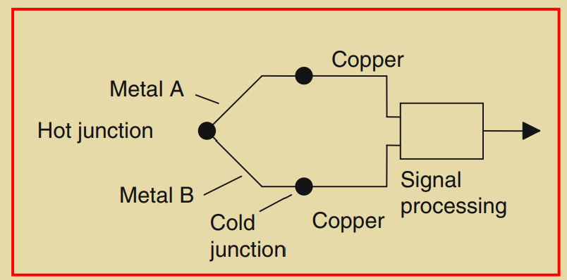
Thermocouples are widely used temperature sensors that rely on the principle of the Seebeck effect. A thermocouple consists of two dissimilar metal wires, usually referred to as the positive (A) and negative (B) wires. These wires are joined together at a measurement point, forming a junction. When the temperature of this junction differs from the reference temperature at the other end of the wires (often referred to as the cold junction), an electromotive force (EMF) is generated that is proportional to the temperature difference.
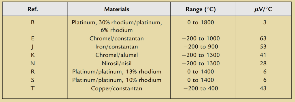
The EMF values generated by thermocouples are specific to the combination of metals used in the thermocouple. These values can be found in reference tables, such as Table 2.2, which assume a reference temperature of 0°C for the cold junction. It’s important to note that the EMF is a small voltage, typically in the millivolt range, and it requires amplification before it can be accurately measured by an analog channel input of a programmable logic controller (PLC) or other measurement devices.
Furthermore, the temperature of the cold junction, which is often at room temperature and not precisely at 0°C, can affect the accuracy of the temperature measurement. Therefore, circuitry is required to compensate for the cold junction temperature and adjust the measured EMF accordingly.
To address these challenges, signal processing units are commonly employed with thermocouples. These units include amplification circuits to increase the small thermocouple voltage to a measurable level, compensation circuits to adjust for the cold junction temperature, and filters to reduce interference from the mains supply and other sources of electrical noise.
Thermocouples offer several advantages, including the ability to sense temperature at almost any point due to their flexibility and small size. They are also known for their ruggedness and durability, making them suitable for harsh environments. Additionally, thermocouples can operate over a wide temperature range, from very low to very high temperatures.
However, thermocouples do have some disadvantages. They provide a nonlinear response, meaning the relationship between the EMF and temperature is not a straight line. Calibration and compensation techniques are required to accurately convert the measured EMF to temperature. Thermocouples also exhibit small changes in EMF per degree change in temperature, resulting in relatively low sensitivity compared to other temperature sensors.
6. Position/Displacement Sensors
Position sensors and displacement sensors are used to measure the distance or change in position of a target object. Position sensors provide a measure of the distance between a reference point and the current location of the target, while displacement sensors measure the distance between the current position of the target and a previously recorded position.
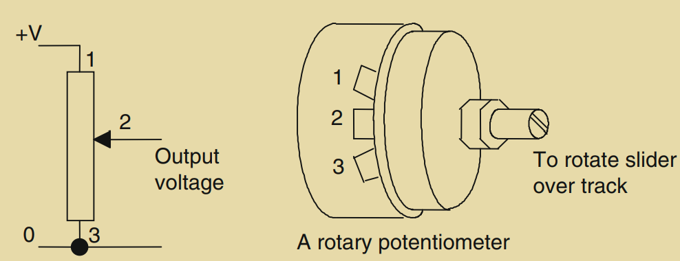
One common type of position sensor is the resistive linear or angular position sensor, also known as a potentiometer. In a resistive potentiometer, a DC voltage is applied across the full length of a resistance track. A sliding contact, connected to the target object, moves along the track, and the voltage signal between the sliding contact and one end of the track is proportional to the position of the contact. This provides an analog output signal that represents the linear or angular position of the target.
Another type of displacement sensor is the linear variable differential transformer (LVDT). An LVDT consists of three symmetrically placed coils and a ferrous rod. When an alternating current is applied to the primary coil, alternating voltages are induced in the two secondary coils. When the ferrous rod is centered between the secondary coils, the induced voltages are equal, resulting in no output voltage. However, when the rod is displaced from its central position, the voltages induced in the secondary coils become unequal, and the difference between the two voltages, or the output voltage, is proportional to the position of the rod. The LVDT output is typically an alternating voltage, which is converted to an analog DC voltage and amplified before being input to the analog channel of a programmable logic controller (PLC) or other measurement devices.
Capacitive displacement sensors operate based on changes in capacitance. They typically consist of parallel plate capacitors, where the capacitance changes when the plate separation, area of overlap, or the presence of dielectric material between the plates changes. These changes in capacitance are converted into electrical signals through signal conditioning, allowing the sensors to provide linear displacement measurements.
In all these cases, the output from the position or displacement sensors is an electrical signal that represents the position or change in position of the target object. This signal is often conditioned, amplified, and converted to a suitable format for further processing or input into control systems such as PLCs.

7. Strain Gauges
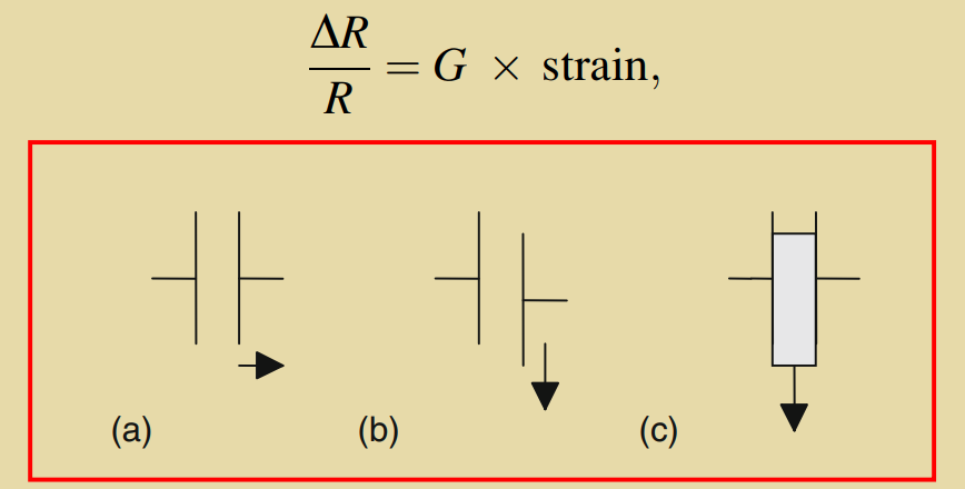
Strain gauges are sensors that detect and measure the strain or deformation in a material. When a wire or strip of semiconductor is subjected to mechanical strain, its resistance changes proportionally to the strain applied. The fractional change in resistance (ΔR/R) is directly proportional to the fractional change in length, which is the strain. The constant of proportionality is known as the gauge factor (G).
Metal resistance strain gauges are commonly used and typically have a gauge factor of around 2. They are often constructed in the form of a flat coil or etched from metal foil. To apply strain gauges, they are attached to a backing material, such as a thin plastic film, which allows them to be easily adhered to surfaces. This enables strain measurements on various objects and structures.
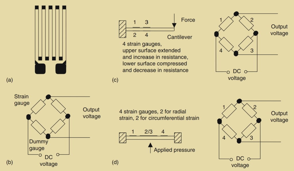
To convert the change in resistance of a strain gauge into a measurable voltage signal, a Wheatstone bridge configuration is commonly employed. The strain gauge is connected as one of the arms of the bridge, and the output voltage of the bridge is proportional to the strain-induced resistance change. However, the resistance of the strain gauge also changes with temperature, which can introduce errors in the strain measurement. To compensate for this temperature effect, temperature compensation techniques are employed.
One common temperature compensation method is to use a dummy strain gauge in an opposite arm of the Wheatstone bridge. The dummy gauge is not subjected to any strain but is exposed to the same temperature as the active strain gauge. This arrangement allows the temperature effects to cancel out, resulting in a bridge output that is primarily influenced by the strain.
Another approach is to use a configuration known as a full-bridge or four-active-gauge configuration. In this setup, four strain gauges are arranged as the four arms of the Wheatstone bridge. Two gauges are placed in tension, while the other two are placed in compression. This arrangement not only provides temperature compensation but also amplifies the output change when strain is applied, improving the sensitivity of the measurement.
By attaching strain gauges to various devices, such as cantilevers or diaphragms, the strain experienced by those devices can be transformed into voltage changes. For example, by attaching strain gauges to a cantilever and measuring the corresponding voltage change, the applied force at the free end of the cantilever can be determined. Similarly, strain gauges attached to a diaphragm can measure the deformation caused by pressure, allowing the pressure to be determined based on the voltage output from the gauges and Wheatstone bridge.
Overall, strain gauges provide a means to convert mechanical strain or deformation into electrical signals, enabling the measurement of forces, pressures, or other physical quantities that cause strain in the monitored devices.
8. Pressure Sensors
Pressure sensors are devices that measure pressure and provide an output signal proportional to the applied pressure. There are different types of pressure sensors available, including diaphragm and bellows types.
Diaphragm pressure sensors consist of a thin disc made of metal or plastic that is secured around its edges. When there is a pressure difference between the two sides of the diaphragm, the center of the diaphragm deflects. The amount of deflection is directly related to the pressure difference. This deflection can be detected using various methods.
One method is by attaching strain gauges to the diaphragm. As mentioned earlier, strain gauges change their resistance in response to mechanical strain. By measuring the change in resistance of the strain gauges, the deflection of the diaphragm and thus the pressure can be determined.
Another method is by utilizing the change in capacitance between the diaphragm and a parallel fixed plate. When the diaphragm deflects, the distance between the diaphragm and the fixed plate changes, resulting in a change in capacitance. This change can be measured and related to the pressure.
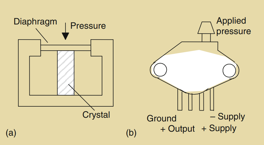
Piezoelectric crystals can also be used in pressure sensors. When a piezoelectric crystal is squeezed or deformed, it generates a voltage proportional to the applied pressure. The deflection of the diaphragm can be used to squeeze the piezoelectric crystal, thereby producing a voltage output that is proportional to the pressure.
One example of a pressure sensor is the Motorola MPX100AP sensor, which utilizes a diaphragm and a built-in vacuum on one side. The deflection of the diaphragm provides a measure of the absolute pressure applied to the other side of the diaphragm. The output of this sensor is a voltage signal proportional to the applied pressure.
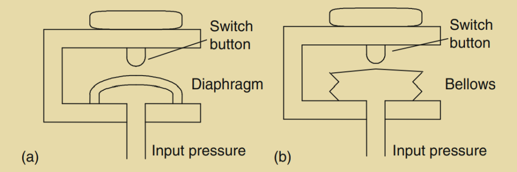
Pressure switches are another type of pressure sensor designed to switch on or off at a specific pressure threshold. They typically employ a diaphragm or bellows that moves under the action of the pressure and operates a mechanical switch. The switch is triggered when the pressure reaches the predetermined level.
In summary, pressure sensors, such as diaphragm-based sensors and those utilizing piezoelectric crystals, provide a means to measure pressure and convert it into an electrical signal. They can be used to measure absolute pressure, gauge pressure, or differential pressure, depending on the design and configuration of the sensor. Pressure switches, on the other hand, are used for pressure-based control applications, where they activate or deactivate a circuit or device at a specific pressure threshold.
9. Liquid-Level Detectors
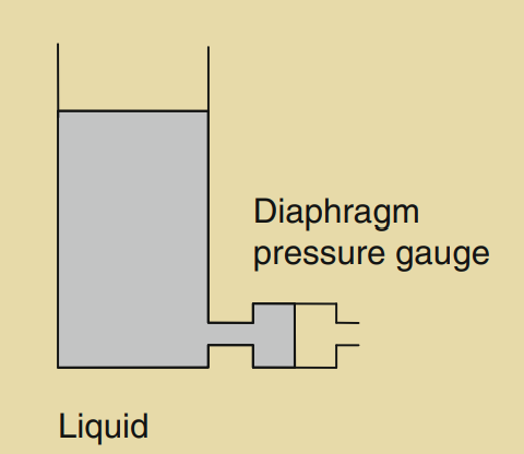
Liquid-level detectors are used to monitor the level of a liquid in a tank or container. One common method for determining the liquid level is by measuring the pressure exerted by the liquid column above a reference point.
The pressure due to a liquid at a height ‘h’ above a reference level can be calculated using the equation P = h * ρ * g, where P is the pressure, ρ is the density of the liquid, and g is the acceleration due to gravity.
To measure the pressure and determine the liquid level, a pressure sensor can be installed at a suitable location in the tank. The sensor measures the pressure exerted by the liquid and provides an output signal proportional to the liquid level.
In some cases, a simple on/off signal is required when the liquid level reaches a particular point. In such instances, a float switch is commonly used. A float switch consists of a float that contains a magnet, which moves within a housing that contains a reed switch. As the liquid level rises or falls, the float moves correspondingly, turning the reed switch on or off. The reed switch is connected to a circuit that can switch a voltage on or off based on the position of the float. This voltage signal can be used to trigger alarms, control pumps, or perform other actions based on the liquid level.
Overall, liquid-level detectors provide a means to monitor and control the level of liquids in various applications, ranging from industrial tanks to residential water systems.
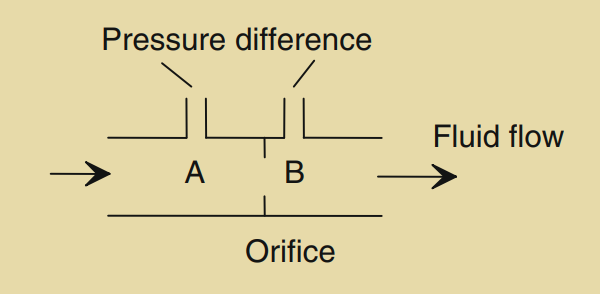
10. Fluid Flow Measurement
Fluid flow measurement is crucial in various industries and applications to monitor and control the rate of fluid movement. One common type of flow meter is based on measuring the pressure difference created by a constriction in the flow path. An example of such a flow meter is the orifice flow meter, as depicted in Figure 2.23.
In an orifice flow meter, a restriction or orifice plate is placed in the flow path of the fluid. As the fluid passes through the constricted area, it experiences a pressure drop. The pressure at point A, upstream of the orifice, is higher than the pressure at point B, downstream of the orifice. The difference in pressure, known as the pressure differential, is directly related to the rate of flow.
To measure the pressure differential and determine the flow rate, a diaphragm pressure gauge or a differential pressure sensor is typically used. The pressure gauge or sensor is connected to points A and B, and it measures the pressure difference between them. This pressure difference is then correlated with the flow rate using calibration curves or equations specific to the orifice flow meter design.
It’s important to note that orifice flow meters require careful calibration for accurate flow measurement. Factors such as the size and shape of the orifice, fluid properties, and installation conditions can affect the accuracy of the measurement. Therefore, proper calibration and consideration of these factors are necessary to obtain reliable flow measurements using an orifice flow meter.
Orifice flow meters are widely used in various industries, including oil and gas, chemical processing, water treatment, and HVAC systems, to monitor and control fluid flow rates.
11. Smart Sensors
Smart sensors are advanced sensor devices that integrate signal conditioning circuitry, data converters, processors, and nonvolatile memory into a single package. Unlike traditional sensors, smart sensors provide additional functionalities beyond sensing, such as data processing, calibration, and communication capabilities. These sensors are designed to simplify the integration and use of sensors in various applications.
The circuitry within a smart sensor includes components like analog-to-digital converters (ADCs), processors, and nonvolatile electrically erasable programmable read-only memory (EEPROM). The EEPROM ensures that important parameters and calibration data are retained even when the power supply is removed. By having all the necessary elements on a single chip, smart sensors can be easily programmed to meet specific requirements and perform complex data processing tasks.
One of the advantages of smart sensors is their ability to compensate for nonlinearities and other sensor-related errors. They can apply correction algorithms to the raw sensor data, providing accurate and reliable measurements. Smart sensors can also have programmable thresholds and trigger warning signals or alarms when a specific condition or threshold is reached.
The IEEE 1451.4 standard interface for smart sensors and actuators focuses on the use of an electronic data sheet format known as TEDS (Transducer Electronic Data Sheet). This standard facilitates easy connectivity between analog transducers and digital measurement systems. The nonvolatile EEPROM memory embedded in smart sensors holds and communicates data, allowing for plug-and-play functionality. The EEPROM can store identification information, sensor properties, calibration data, and other relevant parameters, enabling digital interrogation and seamless integration with measurement systems.
Overall, smart sensors offer enhanced functionality, flexibility, and ease of integration, making them valuable components in modern sensing and measurement applications.