This article is about PLC System. Read Also following topics to understand earlier concepts of
- Lecture 1: What is Programmable Logic Controller in PLC?
- Lecture 2: PLC Hardware Components – PC Information
- Lecture 3: PLC Internal Architecture and Diagram Explanation
What is PLC System? and Working Principle
The two common types of mechanical design for PLC systems are the single-box type and the modular/rack type. Here’s an explanation of each:
Single-Box Type (Compact PLC or Brick):
- The single-box type, also known as a compact PLC or brick, is commonly used for small-scale applications.
- It is a self-contained unit that includes a power supply, processor, memory, and input/output units in a single compact package.
- Typically, these PLCs have a limited number of inputs and outputs, such as 6, 8, 12, or 24 inputs and 4, 8, or 16 outputs.
- The memory capacity of a single-box PLC can store around 300 to 1000 instructions.
- These PLCs are designed for simpler applications where a smaller number of I/O points and program instructions are required.
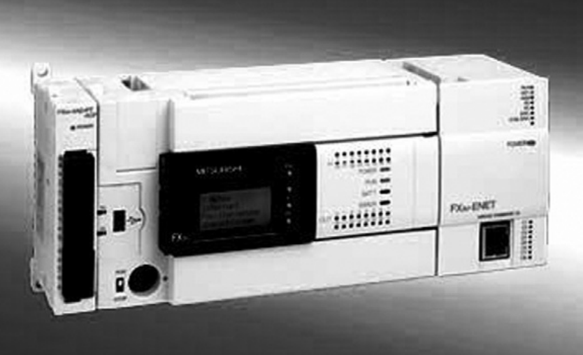
- An example of a single-box PLC is the Mitsubishi MELSEC FX3U compact PLC.
Modular/Rack Type:
- The modular or rack-type PLC systems are designed for larger and more complex applications.
- They consist of a base unit or rack that holds the central processing unit (CPU) and power supply, and can be expanded by adding additional modules or racks.
- The base unit typically contains the processor, memory, and some input/output modules.
- Additional input/output modules can be added to the rack as per the requirements of the application, allowing for scalability and flexibility.
- These modules can be added or removed easily, providing the ability to customize the system based on the specific needs of the application.
- The modular/rack type PLCs are suitable for applications with a larger number of I/O points and more complex control requirements.
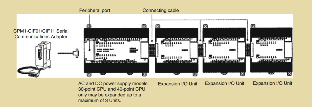
In both types of PLC systems, the inputs and outputs can have different configurations, such as DC or AC inputs/outputs, relay outputs, sinking or sourcing transistor outputs, etc. Expansion units or modules can be added to both single-box and modular PLCs to increase the number of I/O points and capabilities of the system. The specific configuration and expansion options depend on the manufacturer and model of the PLC.

Electronics LLC.)
In systems with larger numbers of inputs and outputs, modular PLC systems designed to fit in racks are commonly used. Here are some key points about modular PLC systems:
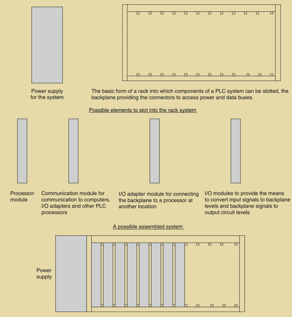
- Modular PLC systems consist of separate modules for the power supply, processor, and other functional units. These modules are often mounted on rails within a metal cabinet.
- The rack-type PLC system can be used for programmable controllers of all sizes. The base rack has sockets where various functional modules can be plugged in according to the user’s requirements.
- The modular design allows for easy expansion of the system. Users can add more input/output modules to increase the number of I/O connections or add more memory units to expand the memory capacity.
- The power and data interfaces for the modules are provided by copper conductors in the backplane of the rack. When modules are inserted into the rack, they engage with connectors in the backplane, establishing the necessary connections.
- An example of a modular PLC system is the Allen-Bradley PLC-5 from Rockwell Automation. PLC-5 processors are single-slot modules that are placed in the leftmost slot of a 1771 I/O chassis.
- The 1771 I/O chassis can be back-panel mounted or rack-mounted and come in different sizes with 4, 8, 12, or 16 I/O module slots.
- A wide range of 1771 I/O modules, both digital and analog, are available for use in the local chassis. Additional modules can also be used at remote locations.
- Digital I/O modules interface with on/off sensors and actuators, while analog I/O modules perform A/D and D/A conversions with up to 16-bit resolution.
- The 1771 I/O modules include features like optical coupling and filter circuitry to reduce signal noise.
- Digital I/O modules cover various electrical ranges from 5 to 276 V AC or DC, and relay contact output modules are available for ranges from 0 to 276 V AC or 0 to 175 V DC. Analog modules support different signal levels, including standard analog inputs and outputs, as well as direct thermocouple and RTD temperature inputs.
Modular PLC systems provide flexibility, scalability, and a wide range of I/O options, making them suitable for applications with larger I/O requirements and complex control needs.
Programs
Programs for PLCs can be written in various formats, but one of the most common and widely adopted methods is ladder programming. Ladder programming was developed to simplify the programming process for engineers with limited programming knowledge.
Initially, different PLC manufacturers had their own versions of ladder programming, which led to inconsistencies. To address this, an international standard for PLC programming was established. In 1993, the International Electrotechnical Commission (IEC) published IEC 1131-3 (sometimes referred to as IEC 61131-3), which standardized the programming methods used for PLCs, including ladder programming.
IEC 1131-3 defines a set of programming languages for PLCs, including:
- Ladder Diagram (LD): Ladder programming is represented by ladder logic diagrams, which resemble electrical circuit diagrams. It uses graphical symbols to represent inputs, outputs, and logic functions such as contacts, coils, timers, and counters.
- Function Block Diagram (FBD): FBD is a graphical programming language that uses blocks to represent functions or operations. It allows users to create complex functions by interconnecting these blocks.
- Structured Text (ST): ST is a high-level programming language that resembles traditional programming languages like Pascal or C. It allows for more advanced programming techniques and is suitable for complex control algorithms.
- Instruction List (IL): IL is a low-level, text-based programming language that uses mnemonic codes to represent instructions. It is similar to assembly language and provides a more direct representation of the underlying machine code.
- Sequential Function Chart (SFC): SFC is a graphical language that represents the sequential flow of control in a program. It is useful for describing complex control sequences and state transitions.
These programming languages defined by IEC 1131-3 provide engineers with a standardized and versatile means of programming PLCs. They enable engineers to choose the most appropriate language for a particular task and promote interoperability among different PLC platforms.
Allen-Bradley PLC-5.
IEC Standard for PLC
The IEC 61131 standard, also known as IEC 1131-3, covers the complete life cycle of PLCs (Programmable Logic Controllers) and provides a comprehensive set of guidelines and specifications. The standard is divided into several parts, each addressing different aspects of PLCs. Here is an overview of the different parts of the IEC 61131 standard:
- Part 1: General definition of basic terminology and concepts: This part establishes the fundamental terminology and concepts used in the PLC domain. It provides a common understanding of key terms and definitions to ensure consistency and clarity in discussions and documentation related to PLCs.
- Part 2: Electronic and mechanical equipment requirements and verification tests for PLCs and associated equipment: Part 2 focuses on the technical requirements and verification tests for the electronic and mechanical components of PLCs and their associated equipment. It specifies the criteria for design, construction, and testing to ensure the reliability and performance of PLC systems.
- Part 3: Programming languages: This part of the standard defines the programming languages that can be used for PLC programming. It includes five languages: ladder diagram (LAD), sequential function charts (SFC), function block diagram (FBD), structured text (ST), and instruction list (IL). Each language has its own characteristics and is suitable for different programming scenarios.
- Part 4: Guidance on selection, installation, and maintenance of PLCs: Part 4 provides guidelines and recommendations for the selection, installation, and maintenance of PLC systems. It covers topics such as system requirements, environmental considerations, installation procedures, and maintenance practices to ensure the proper functioning and longevity of PLC installations.
- Part 5: Software facilities needed for communication with other devices based on the Manufacturing Messaging Specification (MMS): This part focuses on the software facilities required for communication between PLCs and other devices using the Manufacturing Messaging Specification (MMS). MMS is a standard communication protocol used in industrial automation systems.
- Part 6: Communications via field bus software facilities: Part 6 of the standard deals with the communication aspects of PLCs through field bus systems. It provides guidelines for implementing communication protocols and interfaces to enable seamless integration of PLCs with other devices and systems.
- Part 7: Fuzzy control programming: This part addresses the programming of fuzzy control algorithms in PLCs. It provides guidelines and recommendations for implementing fuzzy logic-based control systems using PLC programming languages.
- Part 8: Guidelines for the implementation of PLC programming languages defined in Part 3: Part 8 offers guidelines and best practices for implementing the programming languages specified in Part 3 of the standard. It provides recommendations on syntax, semantics, and programming practices to ensure consistent and efficient use of the defined programming languages.
Programming PLCs
When programming PLCs, there are various programming devices and software tools provided by PLC manufacturers. Here are some common options:
- Handheld programming devices: These devices are portable and typically have enough memory to store programs while being carried from one location to another. They offer basic programming functionalities and are convenient for on-site programming and troubleshooting.
- Desktop consoles: Desktop consoles feature a visual display unit, a full keyboard, and a screen display. They provide a more comprehensive programming environment compared to handheld devices and are suitable for programming and configuring PLCs in a stationary setting.
- Personal computers (PCs): PCs are widely used as program development workstations for PLC programming. PLC manufacturers provide software tools that run on PCs and allow programmers to design, edit, and test programs. Some PLCs require special communication cards to interface with the PC, while others only require the appropriate software.
- Mitsubishi’s MELSOFT: Mitsubishi provides the GX Developer software, which supports their MELSEC controllers. It offers a Windows-based environment and supports programming languages such as IL, LD, and SFC. It includes powerful editors, diagnostics functions, network configuration tools, testing and monitoring functions, and offline simulation capabilities.
- Siemens’ SIMATIC STEP 7: Siemens offers the SIMATIC STEP 7 software, which fully complies with the IEC 61131-3 standard. STEP 7 supports multiple programming languages, including LAD, FBD, IL, ST (SIMATIC S7-SCL), and SFC (SIMATIC S7-Graph). It provides system diagnostic capabilities, process diagnostic tools, PLC simulation, remote maintenance, and plant documentation. S7-PLCSIM is an optional package that allows simulation and testing of programs on a PC before hardware installation.
- Rockwell Automation’s RSLogix: RSLogix is designed for programming the Allen-Bradley PLC-5 family of PLCs. It provides a user-friendly interface and supports ladder logic programming. It offers features such as online editing, simulation, diagnostics, and project documentation.
- OMRON’s CX-One: CX-One is OMRON’s integrated software suite for programming their PLCs. It includes various tools for configuration, programming, simulation, and monitoring. It supports multiple programming languages and provides a comprehensive development environment.
- Telemecanique’s ProWorx 32: ProWorx 32 is the programming software for Telemecanique’s Modicon range of PLCs. It offers a range of programming and configuration features, including ladder logic programming, online editing, simulation, and debugging capabilities.
These programming software packages provide a range of features and functionalities to facilitate PLC programming, debugging, and system configuration, allowing engineers to develop and deploy PLC applications efficiently.
Summary:
A programmable logic controller (PLC) is a specialized type of microprocessor-based controller used for controlling machines and processes. It employs a programmable memory to store instructions and execute functions such as logic operations, sequencing, timing, counting, and arithmetic. PLCs are designed to be operated by engineers who may have limited knowledge of computers and programming languages.
A typical PLC system consists of several functional components:
- Processor Unit: The central processing unit (CPU) of the PLC that executes the instructions stored in its memory.
- Memory: The memory of the PLC stores the program instructions and data that the PLC needs to process.
- Power Supply Unit: Provides the necessary power for the operation of the PLC system.
- Input/Output Interface Section: This section handles the interface between the PLC and the external devices such as sensors and actuators. It provides signal conditioning and isolation functions to ensure compatibility and protection.
- Communications Interface: PLCs often require communication with other devices or remote PLCs. The communications interface allows the PLC to send and receive data over communication networks.
- Programming Device: A programming device is used to create, edit, and transfer programs to the PLC. It can be a handheld device, desktop console, or a computer running specific software provided by the PLC manufacturer.
PLCs rely on the data and program instructions stored in their memory for processing. The input/output channels of the PLC provide the means to connect sensors and actuators directly, often without the need for additional circuitry. The outputs of a PLC can be of different types, such as relay, transistor, or triac outputs, depending on the specific requirements of the application.
The International Electrotechnical Commission (IEC) 61131 standard defines the standards for PLCs. Within this standard, IEC 61131-3 specifically defines the programming languages that can be used for PLC programming. These languages include ladder diagrams (LAD), instruction list (IL), sequential function charts (SFC), structured text (ST), and function block diagrams (FBD). The adoption of these standard programming languages ensures compatibility and consistency across different PLC manufacturers and facilitates easier programming for engineers.