This article is about PLC Internal Architecture and Diagram Explanation.
- Lecture 1: What is Programmable Logic Controller in PLC?
- Lecture 2: PLC Hardware Components – PC Information
PLC Internal Architecture
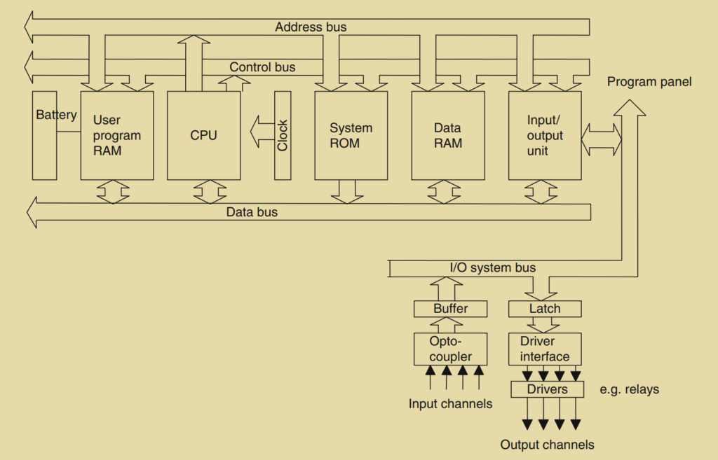
The internal architecture of a PLC, as shown in Figure 1.7, consists of several key components that work together to control and process operations. The central processing unit (CPU) lies at the heart of the PLC and is responsible for executing instructions, performing calculations, and managing data.
Within the CPU, the system microprocessor is the main processing unit that carries out the instructions stored in the PLC’s memory. It performs logical, arithmetic, and timing operations based on the program instructions.
The memory of the PLC holds the program instructions, data, and variables used in the control process. It includes both the read-only memory (ROM) where the PLC program is stored and the random-access memory (RAM) used for temporary storage during program execution.
The input/output (I/O) circuitry is another integral part of the PLC. It interfaces with the external world, connecting the PLC to input devices (sensors, switches, etc.) and output devices (actuators, motors, valves, etc.). The I/O circuitry receives input signals from the external devices and sends output signals to control the external devices based on the program’s instructions.
The CPU operates based on a clock signal, which provides timing and synchronization for all elements within the PLC. The clock frequency, typically between 1 and 8 MHz, determines the operating speed of the PLC.
Digital signals are used to transmit information within the PLC. The internal paths through which these digital signals flow are called buses. The data bus is used for transferring data between different components within the PLC. The address bus carries the addresses of memory locations for accessing stored data. The control bus carries signals related to internal control actions, such as initiating read or write operations. The system bus facilitates communication between the I/O ports and the I/O unit, allowing data exchange between the PLC and external devices.
Overall, the internal architecture of a PLC consists of the CPU, memory, I/O circuitry, buses for data, addresses, and control signals, and the clock that synchronizes the operations. These components work together to execute the PLC program, process data, and control the input and output devices connected to the PLC.
The CPU
The CPU (central processing unit) within a PLC consists of various components that work together to execute instructions and control operations. Here are the key components typically found in a CPU:
- Arithmetic and Logic Unit (ALU): The ALU performs arithmetic operations (such as addition and subtraction) and logic operations (such as AND, OR, NOT, and EXCLUSIVE-OR) on the data within the CPU. It manipulates the data according to the program instructions to carry out calculations and logical comparisons.
- Registers: Registers are small, high-speed memory locations within the microprocessor. They are used to store temporary data and intermediate results during program execution. Different types of registers perform specific functions, such as the accumulator for storing results, the program counter for keeping track of the current instruction, and the status register for storing flags and condition codes.
- Control Unit: The control unit manages the timing and sequencing of operations within the CPU. It coordinates the execution of instructions by fetching them from memory, decoding them to determine the operation to be performed, and controlling the flow of data between different components. The control unit ensures that instructions are executed in the correct order and that the appropriate actions are taken based on the program’s logic.
The internal structure and organization of the CPU may vary depending on the specific microprocessor architecture used in the PLC. However, the ALU, registers, and control unit are fundamental components found in most CPUs. They work together to carry out the processing and control tasks required for executing the PLC program.
The Buses
The buses play a crucial role in facilitating communication and data transfer within a PLC. Here are the four types of buses commonly found in a PLC system:
- Data Bus: The data bus is responsible for transmitting data between the CPU and other components within the PLC. It carries binary information in the form of bits, with each bit transmitted simultaneously along its own parallel wire. The width of the data bus determines the number of bits that can be transferred at a time. For example, an 8-bit data bus can handle 8-bit binary numbers and perform operations on them.
- Address Bus: The address bus is used to transmit the addresses of memory locations within the PLC. Each memory location is assigned a unique address so that the CPU can access and retrieve data from or store data into specific locations. The width of the address bus determines the number of unique addresses that can be represented. For instance, an address bus with 8 lines can address 2^8 (256) distinct memory locations.
- Control Bus: The control bus carries signals that control various operations and functions within the PLC. These signals are used by the CPU to coordinate and synchronize actions. For example, the control bus may include signals to indicate whether data is being read from or written to memory, timing signals for synchronization, and signals for enabling or disabling specific devices or circuits.
- System Bus: The system bus facilitates communication between the input/output ports and the input/output unit of the PLC. It allows data exchange between the PLC and external devices such as sensors, switches, actuators, and communication interfaces. The system bus enables the PLC to receive input signals from external devices and send output signals to control external devices.
The buses provide the necessary pathways for data and control signals to flow within the PLC system, enabling efficient communication and coordination between different components.
Memory
In a PLC system, memory plays a crucial role in storing the program instructions, data, and system-related information. Here are the different types of memory elements typically found in a PLC system:
- System Read-Only Memory (ROM): This memory provides permanent storage for the operating system and fixed data used by the CPU. The contents of ROM cannot be modified by the user and typically include the PLC’s firmware and other system-level data.
- Random-Access Memory (RAM) for User’s Program: This memory is used to store the user’s program, which contains the instructions that dictate how the PLC processes data and controls the system. The program stored in RAM can be modified by the user and allows for flexibility in reprogramming the PLC.
- Random-Access Memory (RAM) for Data: This memory is used to store data related to the status of input and output devices, timer and counter values, and other internal variables. It is often referred to as a data table or register table. Part of the data RAM is allocated for input/output addresses and their states, while other parts are used for preset data, counter values, timer values, etc.
- Erasable and Programmable Read-Only Memory (EPROM): Some PLC systems may include EPROM as an additional memory module. EPROM allows for permanent storage of programs, even when the power supply is switched off. It is commonly used for long-term program storage.
To prevent the loss of programs in RAM when the power is turned off, PLCs typically incorporate a battery backup system. This battery helps maintain the contents of RAM for a certain period, ensuring that programs and data are retained.
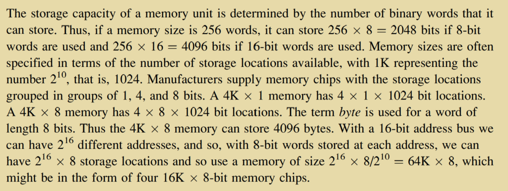
The memory capacity of a PLC is determined by the number of binary words it can store. Memory sizes are often specified in terms of storage locations, with common sizes represented using the “K” notation, where 1K represents 1024 storage locations. Memory chips are available in different configurations, such as 1-bit, 4-bit, and 8-bit groups. For example, a 4K 8 memory chip has 4096 storage locations, each capable of storing an 8-bit byte.
The address bus, which transmits addresses between the CPU and memory, determines the total number of storage locations that can be addressed. For instance, with a 16-bit address bus, it is possible to address 216 (65,536) different memory locations. Using 8-bit words stored at each address, a memory size of 64K 8 (64 kilobytes) can be achieved by using four 16K 8-bit memory chips.
Overall, memory in a PLC system plays a critical role in storing programs, data, and system-related information, allowing for efficient control and operation of industrial processes.
4. Input/Output Unit
The input/output unit in a PLC system serves as the interface between the PLC and the external devices, including input sensors and output actuators. It allows for connections to be made through input/output channels, enabling communication with the outside world. Here are some key points about the input/output unit:
- Input/Output Channels and Unique Addresses: Each input/output point in the PLC has a unique address that is used by the CPU to identify and access specific devices. Similar to houses along a road, each point has a distinct address, such as input address 10 or output address 45, to differentiate between different sensors and actuators.
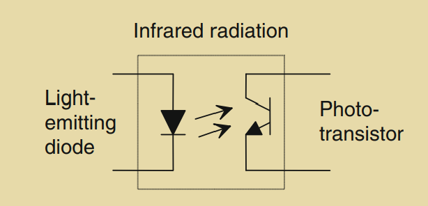
- Isolation and Signal Conditioning: The input/output channels provide isolation and signal conditioning functions. They ensure that sensors and actuators can be directly connected to the PLC without the need for additional circuitry. Electrical isolation from the external world is typically achieved using optoisolators or optocouplers. These components allow a digital pulse in one circuit to generate a corresponding pulse in another circuit while providing electrical isolation.
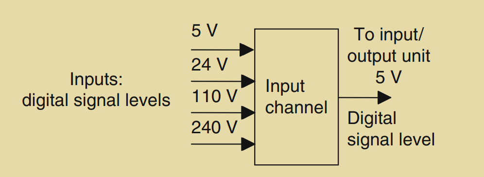
- Digital Signal Compatibility: The digital signals used in PLC systems are generally compatible with the microprocessor and are often set at 5V DC. However, input channels are designed with signal conditioning and isolation capabilities, allowing for a wide range of input signals to be accommodated. Larger PLCs may offer various input signal options, such as 5V, 24V, 110V, and 240V digital signals.
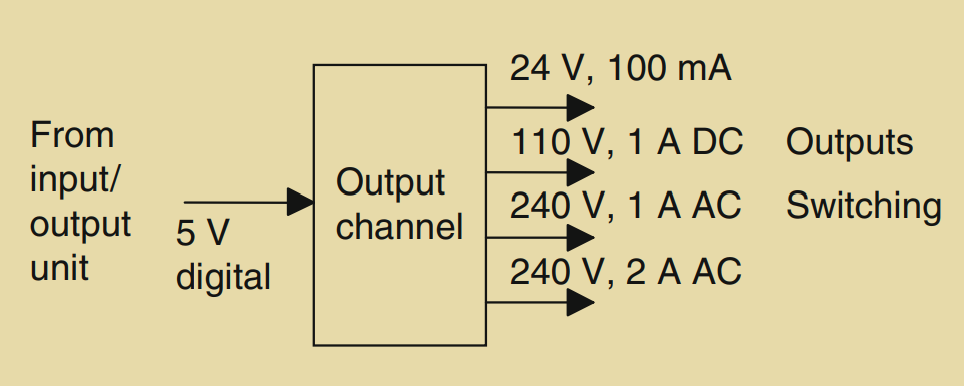
- Output Signal Types: The output signals from the input/output unit are typically digital and have a level of 5V DC. However, after signal conditioning using relays, transistors, or triacs, the output signals can vary. Outputs can be relay type, transistor type, or triac type, depending on the specific requirements.
- Relay Outputs: Relay outputs use the PLC signal to operate a relay, allowing for switching of higher currents in an external circuit. Relays provide isolation between the PLC and the external circuit and can handle both AC and DC switching. They are relatively slower in operation but can withstand high surge currents and voltage transients.
- Transistor Outputs: Transistor outputs utilize transistors to switch current in the external circuit. They offer faster switching action compared to relays but are suitable only for DC switching. Transistor outputs are destroyed by overcurrent and high reverse voltage, so they require protection mechanisms such as fuses or built-in electronic protection.
- Triac Outputs: Triac outputs, combined with optoisolators for isolation, are used for controlling external loads connected to the AC power supply. They are strictly for AC operation and are vulnerable to damage from overcurrent. Fuses are typically included to protect triac outputs.
The selection of input and output types depends on the specific application requirements and the capabilities of the PLC. Modular PLC systems offer flexibility in accommodating a range of input and output options by selecting the appropriate modules.
5. Sourcing and Sinking
Sourcing and sinking are terms used to describe the connection of DC devices to a PLC. They refer to the direction of current flow between the input/output modules and the connected devices. Here’s an explanation of sourcing and sinking:
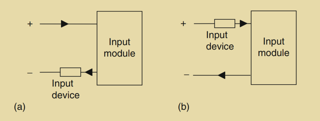
Sourcing:
- In sourcing, the input device or sensor acts as the current source and supplies current to the input module of the PLC.
- With sourcing, the positive (+) terminal of the input device is connected to the positive voltage supply, and the negative (-) terminal is connected to the input module of the PLC.
- The input module receives current from the input device, and the PLC interprets this current as an ON or high state.
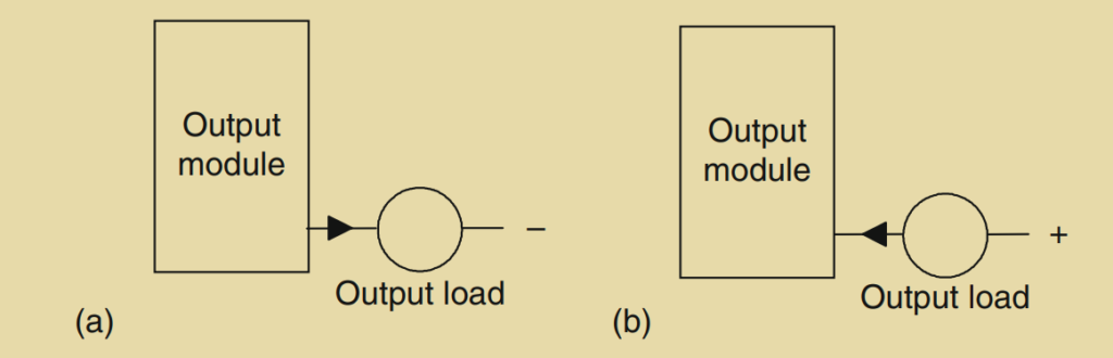
- In the case of output modules, if the current flows from the output module to an external load, the output module is considered to be sourcing current.
Sinking:
- In sinking, the input device or sensor acts as the current sink and receives current from the input module of the PLC.
- With sinking, the positive (+) terminal of the input device is connected to the input module of the PLC, and the negative (-) terminal is connected to the negative voltage supply or ground.
- The input module provides current to the input device, and the PLC interprets the absence of current as an ON or high state.
- In the case of output modules, if the current flows to the output module from an external load, the output module is considered to be sinking current.
It is crucial to determine the type of input or output device being used (whether it is sourcing or sinking) to ensure the correct connection to the PLC. Connecting a sourcing device to a sinking input or vice versa can lead to incorrect operation or damage to the interface. To avoid such issues, sensors with sourcing outputs should be connected to sinking inputs of the PLC, while sensors with sinking outputs should be connected to sourcing inputs of the PLC. Adhering to this guideline ensures proper functionality and prevents damage to the PLC system.