This article is about PLC Hardware Components. A typical PLC system consists of several functional components that work together to perform control tasks.
Lecture 1: What is Programmable Logic Controller in PLC?
PLC Hardware Components
Here is an overview of the basic components:
- Processor Unit or Central Processing Unit (CPU): The CPU houses the microprocessor, which is responsible for executing the control program. It interprets input signals, carries out control actions based on the program instructions, and communicates the output signals to the appropriate devices.
- Power Supply Unit: The power supply unit converts the mains AC voltage to the low DC voltage (typically 5V) required for the processor and other circuitry within the PLC system. It provides the necessary power for the operation of the components.
- Programming Device: The programming device is used by engineers or technicians to develop and enter the control program into the memory of the PLC. It allows for the creation, editing, and transfer of the program to the PLC’s memory unit.
- Memory Unit: The memory unit stores the control program, which contains the instructions for the microprocessor to execute. It also stores data received from input devices for processing and data to be sent to output devices. The memory unit retains the program and data even when the power is turned off.
- Input/Output Interface Section: This section connects the PLC to input devices (e.g., sensors, switches) and output devices (e.g., motors, valves). It interfaces with the external world, receiving input signals from sensors and providing output signals to control devices. The interface section converts the electrical signals between the PLC and the connected devices.
- Communications Interface: The communications interface allows the PLC to communicate with external devices or systems, such as HMI (Human-Machine Interface) panels, SCADA (Supervisory Control and Data Acquisition) systems, or other PLCs. It enables data exchange and coordination between different components of an industrial automation system.
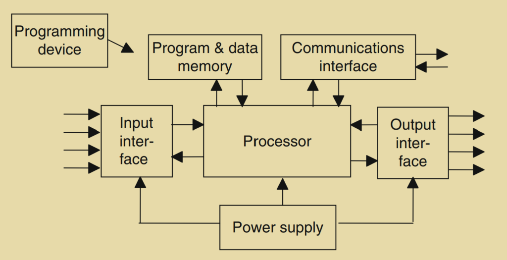
These components work together to form a complete PLC system. The CPU processes the program instructions stored in the memory unit, interacts with the input/output devices through the interface section, and controls the industrial process or machine accordingly. The programming device is used for programming and configuring the PLC, while the power supply unit provides the necessary electrical power for the system’s operation.
How Components Communicate with Each Other?
Indeed, the input and output sections of a PLC system are responsible for receiving information from external devices (inputs) and transmitting information to external devices (outputs). Inputs can come from a variety of sources, including switches, sensors (such as photoelectric cells, temperature sensors, and flow sensors), and other devices that provide discrete or analog signals.
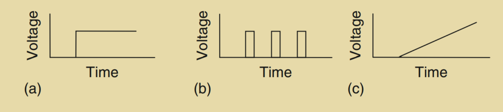
Discrete or digital signals are binary in nature and can be in an on/off state. Examples of devices providing discrete signals include switches, push buttons, limit switches, and proximity sensors. These devices typically generate digital signals that indicate the presence or absence of an event or condition.
Analog signals, on the other hand, provide continuous variable information. They are proportional in magnitude to the measured variable. For instance, a temperature sensor may produce an analog voltage signal that represents the temperature value.
Output devices connected to a PLC can include motor starter coils, solenoid valves, indicators, alarms, and other devices that actuate physical components or provide visual or audible feedback.
The communications interface in a PLC system enables communication between the PLC and other devices or systems. It allows for data exchange, coordination, and integration with external devices, such as Human-Machine Interface (HMI) panels, Supervisory Control and Data Acquisition (SCADA) systems, or other PLCs. The communications interface facilitates tasks like device verification, data acquisition, synchronization between user applications, and connection management.
Overall, the input/output sections and communications interface play crucial roles in enabling the PLC system to interact with the external world, gather input signals, control output devices, and communicate with other devices or systems in an industrial automation environment.