1. General
2. Definitions
3. References
4. Tools and Equipment
5. Methodology
6. Responsibilities
7. Quality Control/Assurance requirement
8. Safety Action Plan
9. Loss Prevention Plan
10. Sketch of used hose
11. Attachment:
Job Safety Analysis
1. Pouring Concrete Procedure of Walls | Method Statement
Scope
Concrete pouring for walls in accordance with the requirements of CONTRACTOR / COMPANY drawings, specifications & standards.
2. Purpose
The purpose of this Method Statement is to describe in detail the appropriate requirement for concrete pouring of walls.
Objective
To ensure execution of concrete pouring for AFD 010 walls are meeting with all quality and safety requirements under the above referenced project.
2. DEFINITIONS:
Method Statement : A written document that gives specific instructions on how to perform a work related task safely or safe operation plan using tools and equipment.
3. REFERENCES:
The latest revision of COMPANY’s Project Specifications shall be used as references and shall be the part of this Method of Statement during work execution.
• SAES-Q-001 – Criteria for Design & Construction of Concrete Structures.
• SAES-O-100 – General Requirements Safety and Security
• SAES M-100 – Saudi Aramco Building Code.
• 09-SAMSS-088 – Aggregates for Concrete
• 09-SAMSS-097 – Ready- mixed Portland Cement Concrete
• SATIP-Q-001-02 – ITP for Cast-In-Place Portland Cement Concrete
• ACI 117 – Standard Specification for Tolerances for Concrete Construction and materials.
• ACI 301 – Specifications for Structural Concrete
• ACI 304R – Guide for Measuring, Mixing, Transporting and Placing Concrete.
• ACI 305R – Hot weather concreting.
• ACI 308 – Standard Recommended Practice for Curing Concrete.
• ACI318 – Building Code Requirements for Structural Concrete.
• ACI 347R – Guide to Formwork for Concrete
• ASTM C39 – Standard Test Methods for Compressive Strength of Cylindrical Concrete Specimens
• ACI224R-01 -Control of Cracking in Concrete Structure.
4. TOOLS AND EQUIPMENT:
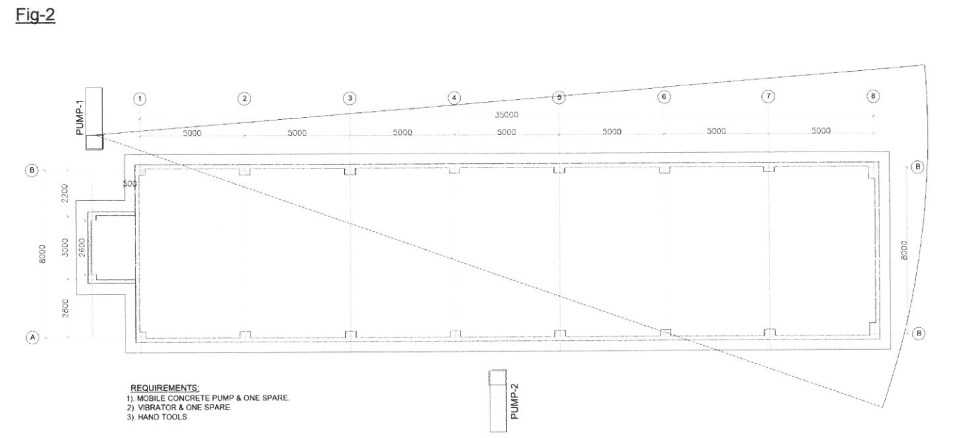
1. Two Mobile Concrete pumps & one Spare.
2. One Air compressor.
3. One Generator.
4. 4 Vibrators plus two spare.
5. Hand tools.
5. METHODOLOGY:
5.1 Definition Areas of (AFD # 010)
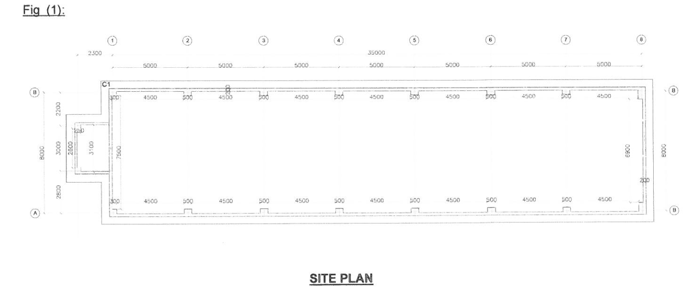
(AFD # 010) Area is as follows Grid A-B/1-8; refer to Fig # (1)
5.2 Pouring sequences
5.2. 1 Pouring Area. pour all concrete wall of AFD building in one time to the required level below the beams of concrete slab with total height 5400mm using one pump truck (And one spare).
5.2.2 Concrete pouring will be done in five uniform layers without forming any cold joint as per requirement and to avoid any segregation. bleeding or bulging of formwork.
5.3 Measuring, Mixing, Transporting & Placing of Concrete:
• Concrete measuring, mixing. transporting and placing shall be in accordance with ACI 304R &09 SAMSS-097.
• Two ready mixed concrete trucks per one pump car shall be planned as the normal ratio. Rates of placing shall be carefully determined to ensure continuous supply of concrete to avoid any cold joint.
5.3.1 Pre-Pouring of Concrete :
• Site concrete pour shall be properly scheduled to ensure that all work has been completed and inspected by QC Inspector of COMPANY & CONTRACTOR to proceed for concrete pouring, adequate manpower and equipment.
• The contractor shall obtain approval from Aramco for the sources of all materials used in concrete including the ready mix batching plant by duly furnishing the valid calibration certificated of the batching plant issued by approved calibrating agencies and test certificates of all concrete ingredients from Aramco approved independent laboratories.
• Before concreting, necessary approval for rebar, formwork should be obtained from Aramco engineer. Clearance from electro mechanical shall be obtained. All the inserts, fixtures are in firmly position.
• All the equipment necessary for the proposed concrete should be made available in working condition at site. Proper lighting arrangements should be made available at concreting location if required.
• Adequate manpower shall be arranged at site for finishing the concrete before it takes initial setting.
• Ensure that the correct grade and required quantity of concrete is ordered from approved batching plant and the delivery of concrete shall be such that there should not be any time gap which shall lead to cold joints in the freshly placed concrete.
• Concrete cover to reinforcement starter bars is correct and has not been displaced during pouring works.
• Adequate windows in shuttering will be provided at adequate intervals for placement of concrete.
5.3.2 Placement of Concrete:
- Concrete pouring sequence shall be meet with requirement of Sec 5.2 of this method statement.
- Concrete shall only be placed on surface ready to receive it. Concrete shall be placed gently to avoid segregation and care must be taken to see that the reinforcement is completely surrounded by the concrete and no voids or cavities left in the body of the concrete. It shall generally be deposited in horizontal layers to a compacted depth.
- Under no circumstances water shall be added to the mixer in transit to the site.
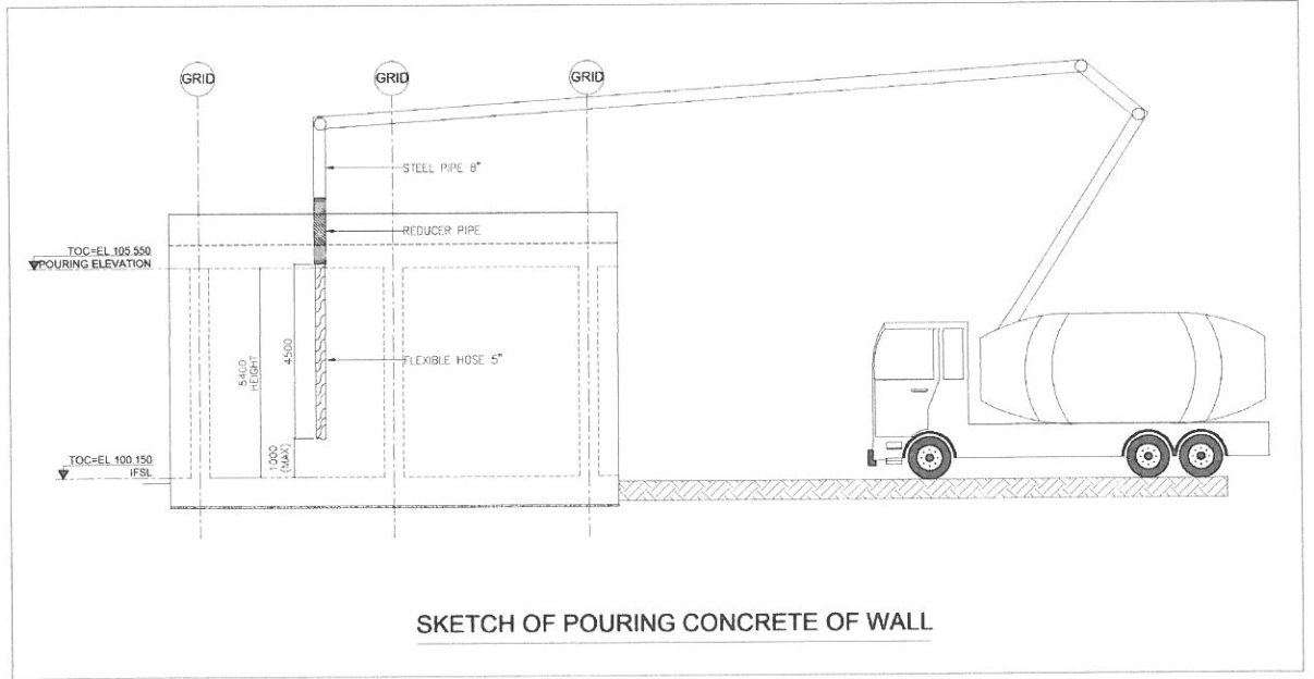
- Concrete shall not be thrown or dropped from a height exceeding 1 m and it shall be placed in final position.
- Concrete shall be thoroughly compacted by vibration during the operation of placing and thoroughly worked around the reinforcements, embedded fixtures and the corner of the formwork to form a solid mass free from voids.
- Maximum height of pouring shall not exceed 1000mm.
- Vibrator shall be inserted vertically, shall penetrate the rapidly to the bottom of the uppermost layer and at least 150mm into the previous lift.
- Insertion of the vibrator shall be such that the fields of action shall overlap.
- Vibration shall stop when the concrete surface takes on sheen, large air bubbles no longer escape, the vibrator pitch or tones changes or the vibrator action changes.
- The vibrator shall not be forced into the concrete or not be used to move the concrete along the form or from one location to another.
- Care shall be taken that the vibrator shall not loosen bolts of the form ties.
- Wood hammer can be used to compact the outside of the frame, only as additional compaction due to lack of efficiency.
- Vibrator shall touch neither the rebar nor the forms during placing of concrete.
- Concrete shall be poured continuously to avoid cold joint.
- To prevent segregation of aggregate concrete shall be placed as near as possible to its final location.
- Pouring concrete using reducer pipe from 8″ of pump steel hose to flexible hose 5″ to reach to bottom areas of walls to avoid segregation.
- Embedded plates and bolts are in the correct location. This will be verified by the Surveyor or Engineer immediately after placing concrete is complete.
- After concrete has been consolidated, rough finishing shall be performed at the top of concrete to provide bond for slab concreting.
5.3.3 Post – Placement of Concrete:
- On completion of concreting, the site shall be cleaned and any splashes of concrete shall be removed to avoid setting and hardening.
- Curing Mat. PVC Sheet, Water Tanker should be prepared prior to concrete placing works commencing.
- Curing of concrete shall be made from the next day and if the weather is hot, proper protection arrangement shall be in place to protect the concrete from quick drying. Curing shall be arranged continuously as per requirement
- Stripping of formwork will be done as mentioned in SAIC-Q-1016.
5.3.4 Repair
- Touching up of concrete surfaces after the removal of form work is not permitted until they have been inspected and released in accordance with the quality procedures.
- Special attention shall be paid to the limitation of the cracks in the concrete.
- All repair works shall be done in accordance to Project Specification.
6. Responsibilities:
6.1 Site Manager
The Site Manager has the overall responsibility for the implementation of work as per approved drawings. He shall arrange the manpower, equipment and materials required for the implementation of the works, coordinate with HSE Officer and QA/QC Site Manager involved in the tasks in accordance to the method statement and responsible for implementing HSE.
6.2 QA/QC Site Manager
The QA/QC Site Manager shall be responsible for ensuring that works are carried out in accordance with relevant procedures, ITP and quality requirements.
6.3 HSE Supervisor
HSE Supervisor is responsible for ensuring implementation of HSE and HSE officer monitors implementation.
6.4 Site Building Engineer
The Site Building Engineer has the overall responsibility for the implementation of work as per approved drawings. He shall arrange the manpower, equipment and materials required for the implementation of the works, coordinate with HSE Officer and QA/QC Site Manager involved in the tasks in accordance to the method statement.
6.5 Site Supervisor
The Site Supervisor is the in-charge for the implementation of the work activities as per approved
drawings. Also, the Site Supervisor is responsible for securing and closing out of all PTWs.
6.6 Q.C (Inspector)
The QC inspector is responsible of compliance of the work was done and arrange the
request for inspection with the client
6.7 Surveyor
The Surveyor is responsible for stake out the locations I boundaries, elevation, alignment and other
related survey activities.
7. Quality Control & Assurance Requirement:
All materials, workmanship and inspection shall conform to all Saudi Aramco Typical Inspection Plan, Saudi Aramco Inspection Checklist, Construction Specification, Standard Drawings and IFC Drawings.
8. Safety Action Plan:
• Sub-contractor’s Safety Supervisor shall carry out the safety site inspections to ensure that safety requirements laid out in the safe work plan are followed during and after the work activities. All applicable requirement set forth by COMPANY HSE Standards shall be followed.
• Subcontractor’s Safety Department together with main contractor’s safety team and COMPANY safety representatives shall inspect the site prior to commencement of the works.
• The safety department shall ensure that all the requirements in relation to concrete works are to be followed.
• No work is to start prior to complete safety clearance and relevant work permits to be issued by COMPANY Operation.
• Prior to preparation, all related safety requirements in this work shall be secured by the supervisor responsible and inspected by sub-contractor Safety Manager I Supervisor.
• Unnecessary material should be removed to prevent the tripping hazard.
• Ensure to provide temporary wooden planks walkways during the rebar work to prevent fall.
• Every job can be done safely.
• Safety access should be provided.
• All timbers are to be de-nailed immediately they are removed and nails are to be placed in a used nail box.
• Site supervision and managers to inspect and ensure area is safe.
9. Loss Prevention Plan:
• No person shall be expected or required to work in unsafe or unhealthy working environments.
• Each person shall be competent and capable of safety performing any work required of them.
They shall be suitable experienced, qualified and physically fit, and they shall have proper instruction, training and supervision provided.
10. Sketch (Used Hose in Pouring):


