This article is about Applicable Codes and Standards for Pressure Piping System as per international codes and standards and SAES-L-100.

Codes and Standards for Pressure Piping System
The SAES-L-100 standard serves as a comprehensive guideline for the design, construction, and inspection of piping systems under the ownership or operation of Saudi Aramco. This standard specifically references the ASME B31.1, B31.3, B31.4, and B31.8 Codes, collectively known as the Codes, which provide essential regulations for various aspects of piping systems.
The primary purpose of SAES-L-100 is to establish a structured framework that facilitates the integration of Saudi Aramco Engineering Standards and Saudi Aramco Materials System Specifications with the applicable Codes. This integration ensures a cohesive and compliant approach to piping system design and implementation.
In essence, SAES-L-100 outlines a set of rules and criteria for the selection and implementation of the relevant Saudi Aramco standards and specifications. These additional standards and specifications are chosen to supplement the provisions of the Codes, enhancing the quality, safety, and reliability of the piping systems within the scope of Saudi Aramco’s operations.
1. International Codes and Standards
American Society of Mechanical Engineers
ASME B31.1 – Power Piping
ASME B31.3 – Process Piping
ASME B31.4 – Pipeline Transportation Systems for Liquid Hydrocarbons and Other Liquids
ASME B31.8 – Gas Transmission and Distribution Piping Systems
2. Governing Codes and Standards
The governing codes and standards outlined in this section establish the foundation for the design, construction, and inspection of pressure piping systems within Saudi Aramco. These regulations ensure the integrity, safety, and performance of these systems, contributing to the reliable operation of various industrial processes. Let’s delve into the key points highlighted in this excerpt:
5.1 Selection of ASME B31 Codes:
All pressure piping systems within Saudi Aramco are subject to design, construction, and inspection based on a pre-selected ASME B31 Code as a minimum requirement. The choice of the specific ASME B31 Code is detailed in Section 6 of the standard. This standardized approach ensures that a recognized industry code is adhered to, forming the basis for system design and operation.
5.2 Compliance with Saudi Aramco Standards:
In addition to the selected ASME B31 Code, all pressure piping systems must also adhere to applicable Saudi Aramco piping standards, as outlined in Section 7 of the standard. This dual requirement emphasizes Saudi Aramco’s commitment to maintaining high levels of safety, quality, and performance in its piping infrastructure.
5.3 Adoption of Latest ASME B31 Codes:
All piping standards, whether ASME B31.1, B31.3, B31.4, or B31.8, must incorporate the latest editions of the corresponding ASME B31 Codes for pressure piping. This practice ensures that the most up-to-date and relevant guidelines are followed during the design, construction, and inspection processes.
5.4 Resolution in Cases of Unclear Code Application:
In situations where the appropriate code or standard is not explicitly identified or clear selection cannot be achieved, the Piping Standards Committee Chairman is responsible for making a resolution during the initial stages of project development. This proactive approach ensures that decisions align with industry best practices and regulatory requirements.
5.5 Non-Retroactive Standards Revisions:
Standards revisions are not retroactively mandated for piping systems that were constructed before the approval dates of these revisions. This provision recognizes that existing systems may have been designed and built according to earlier standards and provides clarity on the applicability of revised standards to pre-existing infrastructure.
Exclusions from ASME B31 Piping Codes:
Certain services fall outside the scope of the ASME B31 piping codes. These exclusions include sanitary and gravity sewers with specific pressure limitations, plumbing systems within buildings, stacks, flues, vents, and ducts for various purposes, tubes and fittings for specialized equipment, and specific wellhead assemblies for oil, gas, and water wells.
These governing codes and standards serve as a framework that guides the design, construction, and inspection of pressure piping systems within Saudi Aramco. By adhering to these regulations, Saudi Aramco ensures the reliability, safety, and performance of its piping infrastructure across various industrial operations.
3. Applicable ASME Codes for Pressure Piping System
The sections provided outline the specific categories of piping systems and their corresponding applicable ASME Codes within the context of Saudi Aramco’s regulations. These designations ensure that various types of piping systems are built and operated in compliance with the appropriate industry standards. Let’s break down the key points mentioned in this excerpt:
6.1 Power Piping (ASME B31.1):
Piping systems falling within the realm of power generation are designated as Power Piping and must adhere to the ASME B31.1 Code. This category encompasses steam power generation plants, co-generation plants, and steam generating plants. These facilities are required to meet the standards set forth by ASME B31.1 to ensure the safe and efficient operation of power generation processes.
6.2 Process Piping (ASME B31.3):
Refineries, petrochemical plants, gas oil separation plants (GOSP), gas plants, NGL plants, offshore platforms (except for certain sections beyond code break points), and steam generating facilities within a process piping facility all fall under the designation of Process Piping. Compliance with the ASME B31.3 Code is essential for maintaining the integrity of these systems involved in various industrial processes.
6.3 Transportation Piping (ASME B31.4):
Piping systems in liquid service, intended for the transportation of liquids such as hydrocarbons, water, and NGLs, are designated as Transportation Piping. This category includes cross country pipelines, water injection systems, NGL transportation pipelines, terminals for crude oil and derivatives, bulk plants, tank farms, and more. These systems must meet the ASME B31.4 Code, ensuring the safe transport of liquids.
6.4 Transportation Piping in Gas or Multi-Phase Service (ASME B31.8):
For piping systems involved in the transportation of gas or gas-liquid mixtures, compliance with the ASME B31.8 Code is mandated. This category covers cross country pipelines in gas service, flowlines, testlines, gas compression stations, sub-sea flowlines, and more. The ASME B31.8 Code sets the standards for gas and multi-phase transportation systems, emphasizing safety and efficiency.
6.5 Skid Mounted Piping (Applicable Code):
Shop fabricated skid mounted piping, like metering skids, must adhere to the applicable Code selected for the facilities where they will be installed. This provision ensures that these skid-mounted systems align with the specific requirements of the designated facilities.
By categorizing piping systems and assigning them to the appropriate ASME Codes, Saudi Aramco establishes a structured framework for designing, constructing, and operating these systems. This approach ensures that each type of piping system adheres to the industry’s best practices and safety standards, contributing to the overall reliability and performance of Saudi Aramco’s operations.
4. Applicable Saudi Aramco Standards
The provided sections outline the usage of Saudi Aramco’s own standards (SAES-L series) in the context of designing and constructing pressure piping systems. Here’s a breakdown of the key points in this excerpt:
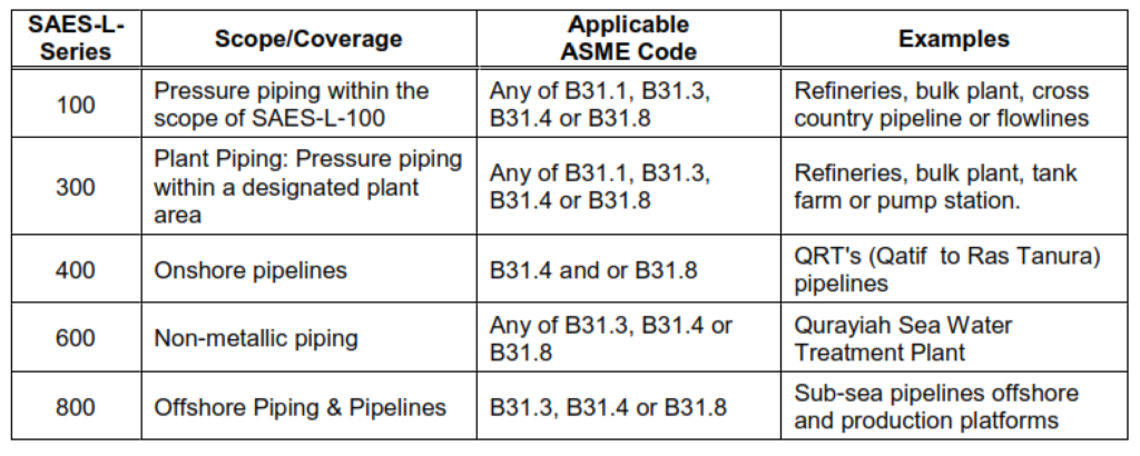
7.1 Structure of SAES-L Piping Standards:
The SAES-L series of piping standards follow a structured format as detailed in Table 1. This structure likely includes various sections, guidelines, and specifications that cover different aspects of pressure piping systems. This standardized format ensures consistency and clarity across the SAES-L series, making it easier for engineers and stakeholders to navigate and implement the standards effectively.
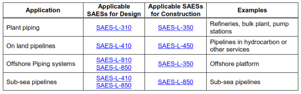
7.2 Applicable SAES for Pressure Piping:
All pressure piping systems falling within the scope of this standard must be designed and constructed in accordance with the applicable SAES (Saudi Aramco Engineering Standards) as assigned in Table 2. The SAES provide specific guidelines and requirements that are tailored to Saudi Aramco’s operations and industry practices. Adhering to these standards ensures that pressure piping systems are built to the highest quality and safety standards.
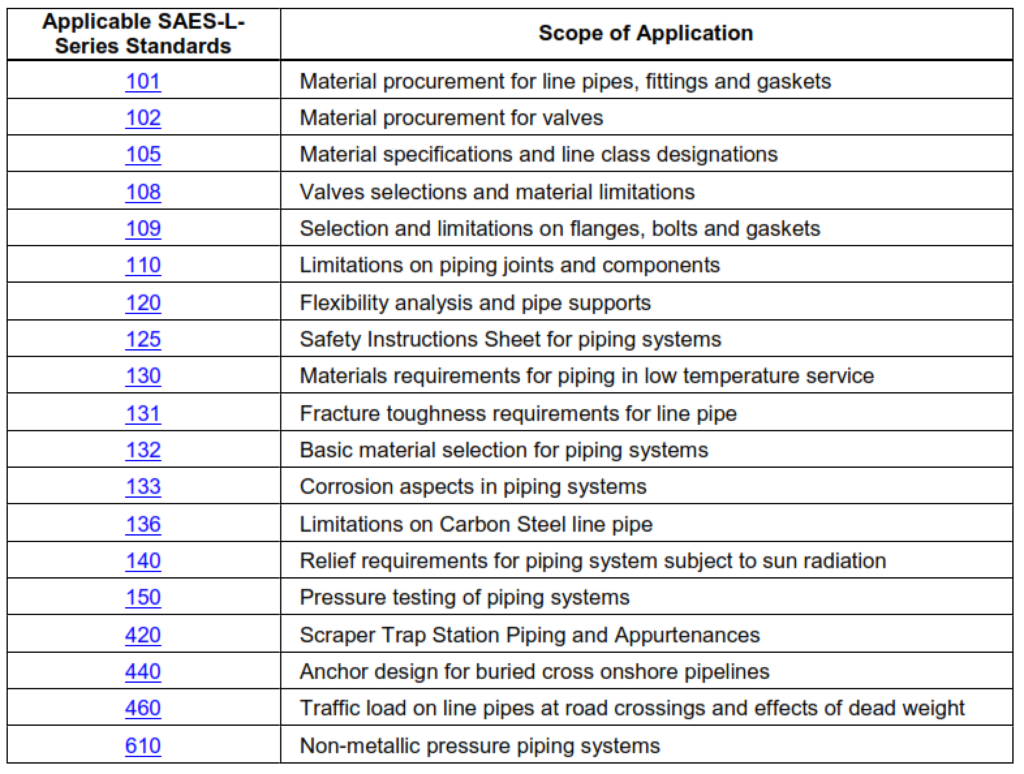
7.3 Compliance with Listed Standards:
Pressure piping systems within the scope of this standard are also required to comply with the standards listed in Table 3. These standards likely include internationally recognized codes and specifications that cover various aspects of piping design, construction, and operation. Complying with these standards ensures that the pressure piping systems are in line with best practices and industry norms.
The integration of SAES-L standards in conjunction with other established industry codes and standards ensures that pressure piping systems operated by Saudi Aramco adhere to both the company’s specific requirements and broader industry norms. This comprehensive approach to standards helps maintain the safety, reliability, and efficiency of the pressure piping systems across Saudi Aramco’s operations.
5. Code Break and Plot Limits for Pressure Piping System
This section explains into the concept of code breaks and plot limits within the framework of piping systems. Here’s a breakdown of the key points in this excerpt:
8.1 Definition and Establishment of Code Break:
The code break, which marks the boundary between different codes for piping systems, needs to be clearly defined and established early in the design stage. If the exact location of the code break isn’t determined according to paragraph 8.4, factors like safety, practicality, and economic considerations should guide the selection of the physical location.
8.2 Alterations to Existing Code Breaks:
Existing code breaks should not be changed to meet new requirements or to match newly assigned code breaks within specific facilities. Any alterations to existing code breaks require joint approval from various stakeholders, including the Piping Standards Committee Chairman, Proponent Representative, Loss Prevention, PMT, and CSD. This ensures that changes are thoroughly evaluated and agreed upon.
8.3 Determining Code Break Locations:
Code break boundaries between different codes should be on the side of the more stringent code, resulting in the higher pipe class. Several recommended locations for code breaks are provided, each suitable for different scenarios and types of piping systems. These locations help maintain clear distinctions between different codes and standards.
8.4 Code Break Locations:
The recommended locations for code breaks are elaborated, considering both onshore and offshore scenarios. These locations include:
- Plot limits boundary, preferably at the plot limit valve.
- Emergency isolation valves near the perimeter fence.
- The isolation valve on the lateral line of an onshore scraper launcher receiver trap.
- For offshore piping, specific points on the riser or drop-out spool are designated as code break points.
- In cases of piping systems designed for instrument scraping capabilities, the code of the pipeline is extended to the launcher/receiver barrel.
By clearly defining code breaks and plot limits and adhering to established guidelines, Saudi Aramco ensures consistency and adherence to codes and standards in its piping systems. This approach contributes to the overall safety, reliability, and effectiveness of the piping infrastructure across various operational scenarios.
6. Pressure Piping System Design Basis
In this section, the general design basis for piping systems within the Saudi Aramco context is outlined. Here are the key points covered:
9.1 Responsibility for Design Parameters:
The Design Agency responsible for designing piping systems for Saudi Aramco must identify the applicable design parameters according to the relevant codes. This ensures that the design is aligned with the necessary standards and regulations.
9.2 Contingent Design Conditions:
Piping systems are not typically designed for double contingency unless such a possibility arises from Hazard and Operability (HAZOP) studies. Various examples of contingent design conditions are provided. These include scenarios like uncontrolled plant shutdowns, improper operations due to single acts or decisions, device or function failures, fire occurrences in fire hazardous areas, adverse ambient conditions, and coincident unrelated contingencies or failures.
9.3 Protection Philosophy:
The general protection philosophy for piping systems in Saudi Aramco is that these systems should be mechanically capable of withstanding design conditions as required by applicable codes. This emphasis on mechanical capability contributes to the reliability and safety of the piping infrastructure.
9.4 High Integrity Protection Systems (HIPS):
The application of High Integrity Protection Systems (HIPS) follows the guidelines provided in the relevant Saudi Aramco standards, such as SAES-L-310 or SAES-L-410, based on applicability. HIPS plays a crucial role in enhancing the safety and protection features of piping systems.
9.5 Critical Piping Identification:
Certain piping systems are classified as Critical Piping. This classification is based on specific criteria, such as being part of vital plant equipment, essential for plant operation at design capacity, not easily replaceable using local materials, vulnerable to damage from fire or explosion, and serving hydrocarbon service (excluding lube oil and seal oil).
By adhering to these general design principles and criteria, Saudi Aramco ensures that its piping systems are designed to withstand various operational conditions and contingencies while prioritizing safety, integrity, and optimal performance across its facilities.