Following contents to be discussed for Pressure Regulators Selection Notes, How to use a Pressure Regulator, Pressure Reducing Regulator, Pressure Regulator Sizing Calculation, Relieving Pressure Regulator.
1. Scope
2. General
3. Overpressure Protection
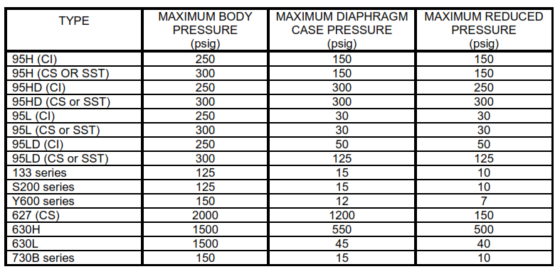
TABLE I – Pressure Specifications for Commonly Used Fisher Rosemount Company Pressure reducing Regulator.
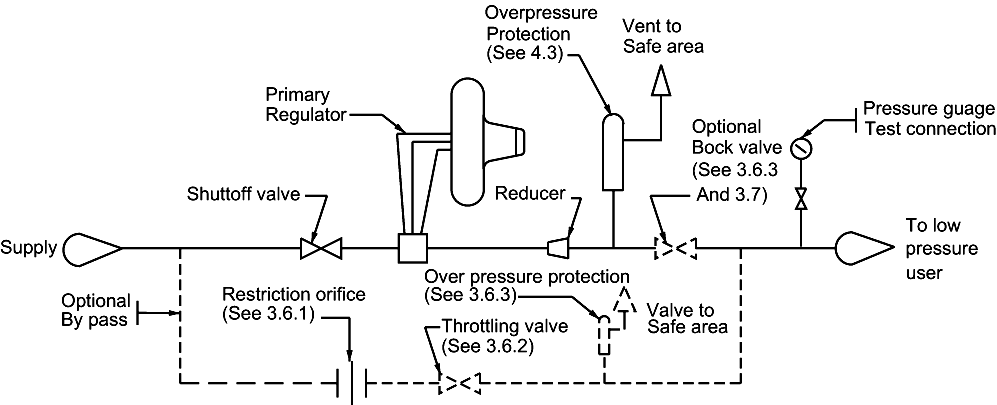
FIGURE 1 – Typical Piping Diagrams.
Figure 1A. Supply Pressure 60 psig or Less But Greater than the Maximum Allowable Working Pressure of the Low-pressure System.
Figure 1B. Supply Pressure Greater Than 60 psig.
Fundamental Principle:
What is pressure regulator? It is a device which controls the pressure of liquids or gases in plants and industries by reducing a high input pressure to a controlled lower output pressure. They also work to maintain a constant output pressure even when there are fluctuations in the inlet pressure.

1. Scope
This article provides guidance and notes of pressure regulators selection in the design of pressure reducing facilities (Plants and Refineries) to supply gas pressures in the range of 0 to 10 psig for applications such as natural gas to burners and inert gas for blanketing storage tank vapor spaces.
2. Pressure Regulators Selection Notes in Process Industry
2.1 A shutoff valve shall be installed immediately upstream of each pressure regulator. Where more than one regulator is used in series, a single shutoff valve upstream of the combination will be adequate.
2.2 In general, a completely self-contained regulator with no external impulse lines should be selected for these services. It shall be capable of reducing the distribution system pressure to the level required by the user, and regulating it within the necessary limits of accuracy. Where external impulse lines must be used, they shall be provided with suitable mechanical protection and shall be adequately sized to ensure rapid response.
2.3 The regulator throttle valve should be single port with an orifice diameter not exceeding that recommended by the manufacturer for the maximum inlet pressure.
2.4 Regulators with resilient valve seats should be used. These shall be designed to resist cutting by the valve and permanent deformation from being pressed against the valve port and shall withstand the abrasion of the gas and any impurities it may contain.
2.5 Self-contained regulators using a spring and diaphragm mechanism normally are selected for these applications. These regulators are distinguished by their large diameter, flat diaphragm cases.
2.5.1 A diaphragm case vent is necessary for proper operation of this type regulator. Care should be taken to ensure this vent is not restricted or plugged in any way during installation or operation. Where the regulator is mounted in a building or an enclosure, this case vent should be piped outside to a safe, remote location to avoid a possible unsafe condition should the diaphragm develop a leak.
2.5.2 Bodies for these regulators shall conform to the design pressure, temperature, and material of construction specified for valves in the
applicable piping code.
2.5.3 Although the body for this type regulator may be adequately designed for the inlet pressure, the diaphragm case generally does not meet this pressure rating. See Table 1. It must be assumed that any valve will leak through the seat. Therefore, any blocked valves or blockage downstream of the regulator may lead to full supply pressure on the low pressure side of the regulator unless protected by a pressure relief device.
2.5.4 Where the maximum case pressure rating is not known, it must be obtained from the regulator manufacturer.
2.5.5 A straight run of piping the same size as the regulator outlet should be run for a minimum distance of 18 inches downstream of the regulator to ensure proper performance.
2.5.6 The downstream piping must not be restricted. Piping that is too small or temporary hoses used in maintenance shops can cause the regulator to
exceed the diaphragm case design pressure and rupture the case. More following notes and points will be covered here for pressure regulators selection.
2.6 Where operating continuity during regulator servicing is required, a suitably piped bypass shall be provided. See Figure 1.
2.6.1 A restricting orifice shall be provided in the bypass piping upstream of the hand valve used to throttle the bypass flow. This orifice shall be sized to
restrict flow through the bypass to a value less than the capacity of the low pressure system over pressure protection device.
2.6.2 A multiturn, globe body valve, meeting the applicable piping specification requirements, shall be provided for throttling the bypass flow.
2.6.3 If the primary regulator diaphragm case pressure rating exceeds the supply pressure, the downstream block valve may be located between the regulator and the low-pressure system overpressure protection device. When the supply pressure exceeds the diaphragm case pressure rating, the block valve must be located downstream of the overpressure protection device and additional over pressure protection must be provided for operating through the bypass. See Figure 1.
2.7 A block valve shall be provided in the low-pressure line to the gas user where it is necessary to permit firing on alternate fuel, or to bottle up a tank vapor space during regulator servicing periods. Location of this valve relative to the low-pressure system overpressure protection device shall be as recommended in 3.6.3. See Figure 1.
3. Pressure Regulators Overpressure Protection
3.1 Overpressure protection shall be provided to prevent the maximum pressure in the low-pressure system from exceeding a value, which would cause unsafe operation or failure of any connected and properly adjusted low-pressure gas burning equipment or other connected device.
3.2 No overpressure protection is required downstream of the primary regulator when the supply pressure does not exceed the maximum allowable working pressure of the low-pressure system.
3.3 If the process vapor or gas is not flammable, toxic, or corrosive and the supply pressure do not exceed the regulator diaphragm case pressure rating, a single regulator with appropriate overpressure protection for the low-pressure system may be used.
3.4 Where flammable, toxic, or corrosive vapors or gases are to be controlled, overpressure protection shall be provided as follows.
3.4.1 When the supply pressure is greater than the maximum allowable working pressure of the low-pressure system but does not exceed 60 psig, suitable overpressure protection shall be provided downstream of the primary regulator. See Figure 1A.
3.4.2 A first-cut pressure regulator, with its own overpressure protection device, shall be used in addition to a primary pressure regulator and suitable
overpressure protective device when the supply pressure exceeds 60 psig. The first-cut regulator shall be set to maintain a pressure not exceeding 60
psig. See Figure 1B.
3.5 Overpressure protection may be accomplished by any one of the following means:
a. A relief valve of a type meeting the provisions of the ASME Boiler and Pressure Vessel Code, Section VIII, Division 1. This means is easiest to fit
into existing protective device maintenance programs.
b. A first-cut regulator with its own overpressure protective device installed upstream of the primary regulator and set to limit continuously the pressure at the inlet of the primary regulator to the maximum allowable working pressure of the downstream piping system. Recommended when the supply pressure exceeds 60 psig.
c. An automatic shutoff device installed in series with or included as an integral part of the regulator design, set to shut off when the pressure on the
downstream piping system reaches the maximum allowable working pressure or some other predetermined pressure less than the maximum
allowable working pressure. For natural gas burner systems, this type of device must be designed to remain closed when tripped until manually reset.
d. A liquid seal relief device, such as a dip tube submerged in a liquid, which can be set to open accurately and reliably at the desired pressure. It is
limited to systems with very low set pressures.
3.6 The overpressure protection device may be installed as an integral part of a regulator or as a separate unit. In either case, it shall be sized to handle full regulator capacity and shall be installed in such a way as to accommodate testing on a regular basis.
3.7 Discharge stacks, vents, or outlet ports of all pressure relief devices shall be located where gas can be discharged into the atmosphere without presenting a hazard.
3.8 Discharge piping shall be provided with an open drain to prevent accumulation of rainwater or liquid. Where required, provision should be made to prevent birds and insects from building nests in the discharge piping.
TABLE I – Pressure Specifications for Commonly Used Fisher Rosemount Company Pressure-reducing Regulators
FIGURE 1 – Typical Piping Diagrams
Figure 1A. Supply Pressure 60 psig or Less But Greater than the Maximum Allowable Working Pressure of the Low-pressure System
Figure 1B. Supply Pressure Greater Than 60 psig


