1. SCOPE ………………………………………………………………………………………………………………..2. REFERENCES ……………………………………………………………………………………………………………..3. DEFINITIONS ……………………………………………………………………………………………………………….4. INSTRUMENT SIGNAL CABLES …………………………………………………………………………………..4.1. Construction ……………………………………………………………………………………………………………….4.2. General Requirements ……………………………………………………………………………………5. FIBER OPTIC CABLES ……………………………………………………………………………………5.1. General ………………………………………………………………………………………………………………..5.2. Outdoor Cable …………………………………………………………………………………………………………….5.3. Indoor Cable ……………………………………………………………………………………………………………….5.4. Indoor-Outdoor Cable ……………………………………………………………………………………5.5. Multimode 62.5/125 µm ……………………………………………………………………………………5.6. Multimode 50/125 µm ……………………………………………………………………………………5.7. Laser Optimized multimode 50/125 µm …………………………………………………………………………5.8. Single Mode ………………………………………………………………………………………………………………..6. 100 OHM CATEGORY 6 FOUR PAIR UTP CABLES ……………………………………………………….6.1. General ………………………………………………………………………………………………………………..6.2. Basic Features …………………………………………………………………………………………………………….6.3. Construction ……………………………………………………………………………………………………………….6.4. 100 Ohm Category 6 Four Pair UTP Patch Cord ……………………………………………………….7. COAXIAL CABLES ………………………………………………………………………………………………………7.1. General ………………………………………………………………………………………………………………..7.2. Basic Features …………………………………………………………………………………………………………..7.3. Construction ……………………………………………………………………………………………………………..8. INSPECTION AND TESTING ……………………………………………………………………………………8.1. General ………………………………………………………………………………………………………………..8.2. Fiber Optic Cable ……………………………………………………………………………………………………….9. IDENTIFICATION AND TAGGING ………………………………………………………………………………..9.1. Jacket for fiber optic cables ……………………………………………………………………………………10. PREPARATION FOR SHIPMENT …………………………………………………………………………………10.1. Packing ………………………………………………………………………………………………………………..10.2. Reels for fiber optic cables ……………………………………………………………………………………10.3. Reels for other cables ……………………………………………………………………………………10.4. UTP Cables …………………………………………………………………………………………………………….11. REVISION HISTORY …………………………………………………………………………………………………..12. CABLE SPECIFICATION TABLES ……………………………………………………………………………….12.1. ANALOG SIGNAL CABLES ……………………………………………………………………………………12.2. DIGITAL SIGNAL CABLES ……………………………………………………………………………………12.3. TRIAD SIGNAL CABLES ……………………………………………………………………………………12.4. TYPE KX (CHROMEL/ALUMEL) THERMOCOUPLE EXTENSION CABLES …………………12.5. TYPE TX (COPPER/CONSTANTAN) THERMOCOUPLE EXTENSION CABLE ……………..12.6. FIBER OPTIC MULTIMODE CABLES 62.5/125 ……………………………………………………….12.7. FIBER OPTIC MULTIMODE CABLE 50/125 ……………………………………………………….12.8. LASER OPTIMIZED FIBER OPTIC MULTIMODE CABLE 50/125 …………………………..12.9. FIBER OPTIC SINGLE MODE SIGNAL CABLES ……………………………………………………….12.10. FOUNDATION FIELDBUS SIGNAL CABLES (TRUNK and SPUR CABLES)………………..12.11. 100 Ohm CAT6 UTP CABLE ……………………………………………………………………………………12.12. COAXIAL CABLE ……………………………………………………………………………………………………
1. Scope
This specification defines requirements for manufacturing, testing and shipping of multiconductor
electronic instrument, thermocouple cable, fiber optical cable, UTP Cat6 cable and
Coaxial cable.
2. References
Reference is made in this standard to the following documents. The latest issues, amendments
and supplements to these documents shall apply unless otherwise specified.
SABIC Engineering Standards (SES)
X05-E01 Process Control Cable and Wiring
X05-E02 Field Device Cabling to Junction Boxes
SABIC Information Technology Standards (SSITS)
SSITS-NSD-S03 Network Structured Cabling System
American Society for Testing and Materials (ASTM)
ASTM B 3 Standard Specification for Soft or Annealed Copper Wire
ASTM B 33 Standard Specification for Tinned Soft or Annealed Copper Wire for Electrical
Purposes
International Electro-technical Commission (IEC)
IEC 60331 Tests for Electric Cables under Fire Conditions – Circuit Integrity ( Fire Resistant)
IEC 60332 Tests for Electric Cables under Fire Conditions – Circuit Integrity (Fire Propagation)
IEC 60754 Tests on Gases Evolved during Combustion of Electric Cables
IEC 60793-1-1 Part-1.1 Optical fibers -Measurement methods and test procedures – General
and Guidance Edition
IEC 60793-2 Part-2 Optical fibers –Product Specifications – General Edition 6.0
IEC 60794 Optical Fiber Cables-General Specifications
IEC 61034 Measurement of Smoke Density of Cables Burning under Defined Conditions
IEC 61158-2 Fieldbus Standard for Use in Industrial Control Systems – Part 2
IEC 61196 Coaxial Communication Cables – Generic Specifications
Institute of Electrical and Electronics Engineers (IEEE)
IEEE 532 Guide for Selecting and Testing Jackets for Power, Instrumentation and Control
Cables
Instrumentation, Systems, and Automation Society (ISA)
ISA MC 96.1 Temperature Measurement Thermocouples
National Fire Protection Association (NFPA)
NFPA 70 National Electrical Code (NEC)
Process Industry Practices (PIP)
ELSWC05 300 Volt Instrumentation Tray Cable Specification
Telecommunication Industry Association / Electronic Industries Alliance
(TIA/EIA Standards)
TIA/EIA-455-B- Standard test procedures for fiber optic fibers, cables, transducers, sensors,
connecting and terminating devices, and other fiber optic components.
TIA-472C000-B Sectional Specification Standard for Optical Fiber Premises Distribution Cable
TIA-472D000-B Sectional Specification Standard for Optical Fiber Outside Plant Communication
Cable
TIA-472E000 Sectional Specification Standard for Indoor-Outdoor Optical Fiber Cable
TIA-492AAAA-A Detail Specification for 62.5 micron Core Diameter / 125 micron Cladding
Diameter Ia Graded-Index Multimode Optical Fibers
TIA-492CAAB Detail Specification for Class IVa Dispersion-Unshifted Single-Mode Optical
Fibers
TIA/EIA-568-B.2 Commercial Building Telecommunications Cabling Standard.
TIA-568-B.2-10 Transmission Performance Specification for 4-Pair 100 Ohm Augmented
Category 6 Cabling
TIA-598-C Optical Fiber Cable Color Coding
Underwriters Laboratories, Inc. (UL)
UL 1666 Test for Flame Propagation Height of Electrical and Optical Fiber Cables installed
Vertically in Shafts
UL 2250 Instrumentation Tray Cables
3. Definitions
Backbone cable. A backbone cable typically provides connectivity between equipment rooms
in buildings of a plant or campus.
Fiber core. The central region of an optical fiber through which most of the optical power is
transmitted.
Jacket. The jacket provides the cable with a tough, flexible, protective coating, able to withstand
the stresses expected in normal installation and service.
Multimode. Multimode optical fiber is designed to carry multiple light rays within the optical fiber
core. Multimode fiber transmission is used for relatively short distances.
Refractive Index profile. The distribution of the refractive index along a diameter of an optical
fiber
Single Mode. Single-mode optical fiber is designed to carry only a single ray of light (mode).
Single-mode fibers can have a higher bandwidth than multi-mode fibers over long distances.
Abbreviations and Acronyms
A Analog Signal Cables
AA Analog Signal Cables, with Armor
AI Intrinsically Safe Analog Signal Cables
AAI
Intrinsically Safe Analog Signal Cables, with Armor
CMP Communication Plenum
CMR Communication Riser
D
Digital Signal Cables
DA
Digital Signal Cables, with Armor
DI
Intrinsically Safe Digital Signal Cables
DAI
Intrinsically Safe Digital Signal Cables, with Armor
ETL Electrical testing laboratory
FEP Fluorinated Ethylene Propylene
FF
Foundation Fieldbus Signal Cables
FFA Foundation Fieldbus Signal Cables, with Armor
FRPVC Fire Retardant Polyvinyl Chloride
K
KX Thermocouple Signal Cables
KA
KX Thermocouple Signal Cables, with Armor
PE
Polyethylene
R
Triad Digital Signal Cables
RA
Triad Digital Signal Cables, with Armor
RI
Intrinsically Safe Triad Digital Signal Cables
RAI
Intrinsically Safe Triad Digital Signal Cables, with Armor
T
TX Thermocouple Signal Cables
TA
TX Thermocouple Signal Cables, with Armor
VSWR Voltage Standing Wave Ratio
UTP
Unshielded Twisted Pair
1P
Single Pair
2P
Two Pair
3P
Three Pair
8P
Eight Pair
12P
Twelve Pair
16P Sixteen Pair
24P
Twenty Four Pair
36P
Thirty Six Pair
1T
One Triad
2T
Two Triad
8T
Eight Triad
12T
Twelve Triad
4. Instrument Signal Cables
Cable components shall meet the requirements specified below. In addition, cable construction
shall be in accordance with the Cable Specification Sheets outlined in section 11.0.
4.1. Construction
4.1.1. Conductors
a. Instrumentation conductors shall be uncoated, soft annealed, stranded copper per ASTM
B 3, 7 strands minimum.
b. Thermocouple conductors shall be solid alloys.
c. Pairs/triads shall be twisted with a suitable lay to reduce electromagnetic interference.
The lay of the twist shall be as per PIP ELSWC05.
4.1.2. Insulation
a. Individual wire insulation shall be polyvinyl chloride (PVC) with a minimum rating of 90
Deg C. Wire insulation shall be in accordance with UL 2250.
b. In case of fieldbus cables, wire insulation shall be cross linked polyethylene (XLPE) with
a minimum rating of 90 Deg C.
4.1.3. Color Coding and Numbering
a. Instrument cable color codes shall be as indicated on the Section 11, cable types
specification sheets. In multi-pair and multi-triad cables, pair / triad numbers shall be
continuously printed on the white conductor.
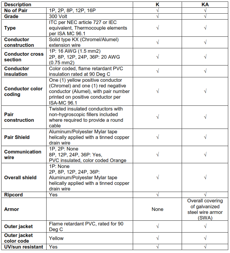
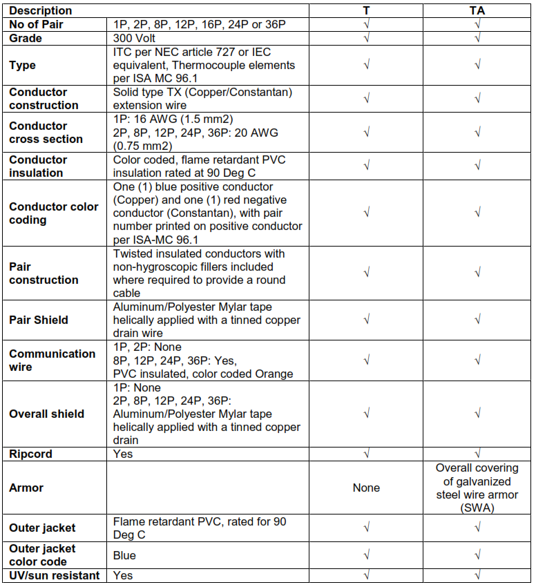
b. Thermocouple cable color codes shall be in accordance with ISA-MC 96.1
4.1.4. Shielding
a. Shielding (when specified) shall consist of an aluminum/polyester Mylar tape with a
stranded tinned copper drain wire applied helically over pairs, triads and multi-conductor
components, with aluminum on the inside in case of single pair or triad shielding and for
multi-pair or multi-triad cables aluminum on the outside.
b. Shield thickness shall be 0.022 mm (0.85 mil) minimum.
c. Helical shield shall be with minimum 25% overlap, to provide 100% coverage and
electrical isolation from conductors.
d. A stranded, circular tinned copper, per ASTM B 33, 7 strands minimum drain wire for
single pair or triad cables shielding, two sizes smaller than the conductors, shall be
provided in continuous contact with the shield.
e. The cable construction shall completely isolate individual shields from each other.
f. A tinned copper drain wire for multi-pair or multi-triad cables shielding of the same size
as the conductors, shall be provided in continuous contact with the overall shield.
4.1.5. Fillers
For multipair/ multi triad cables, the twisted pairs or triads shall be cabled with moisture-
and flame-resistant fillers and an overall binder tape to provide a round cable.
4.1.6. Jacket
a. Unless otherwise specified, PVC cable jacket shall be flame-retardant and resistant to
sunlight, oil, moisture and vapor penetration. Jacket minimum thickness shall be per UL
2250.
b. Jacket/ sheath material selection for cable in chemical, oil etc contaminated areas shall
comply with IEEE 532.
4.2. General Requirements
4.2.1. Multi pair Digital Signal Cables for Solenoid Valves applications shall be minimum 16 AWG
(1.5 mm2) cross section conductor.
4.2.2. Digital Signal Cables for high power solenoids or 120 VAC loads, shall be minimum 14
AWG (2.5 mm2) cross section conductor.
4.2.3. Fire Resistant cables shall comply with IEC 60331, IEC 60332, IEC 61034, IEC 60754.
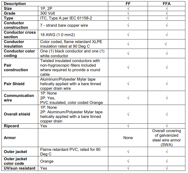
4.2.4. The Foundation Fieldbus Cable shall conform to the IEC 61158-2 section 12.8.2, type A
cable.
4.2.5. Intrinsically Safe cables shall conform to IS requirement per NEC Article 504 or IEC
equivalent. The overall jacket color shall be light blue.
4.2.6. Refer to SES-X05-E02 and SES-X05-E01 for process control cable installation
requirements.
5. Fiber Optic Cables
5.1. General
5.1.1. For FO cables used in IT services, refer to SSITS-NSD-03.
5.1.2. Following shall apply to communication and control systems cables.
5.1.3. Type of optical fibers in the cable shall be as per required specification mentioned by the
equipment manufacturer.
5.1.4. Composite or hybrid cables shall not be permitted.
5.1.5. Following physical requirement shall apply as a minimum to all types of fiber optic cables:
a. Each fiber coating shall be distinguishable from others by means of color coding in
accordance with TIA-598-C.
b. The cable shall contain at least one ripcord under the sheath for easy sheath removal.
c. Cable shall be provided with non metallic central member.
d. Water blocking tapes and water swellable yarns shall be included in the cable
construction to provide water blocking capability for the cable core.
e. The jacket shall be continuous, free from pinholes, splits, blisters, or other imperfections.
f. The jacket shall have a uniform thickness. The outer jacket shall be UV resistant and
smooth.
5.2. Outdoor Cable
5.2.1. Cables used for direct buried outdoor installation shall be armored, double jacketed.
5.2.2. Cables used for underground duct installation shall be unarmored.
5.2.3. Sectional specifications for both types of cables shall comply with TIA-472D000-B or IEC
60794-3.
5.3. Indoor Cable
5.3.1. Cable used for indoor installation shall be plenum unarmored and listed for the application
as per the NFPA-70 Article 770.
5.3.2. Indoor cables shall be fire retardant and halogen free.
5.3.3. Sectional specifications for indoor fiber optic cables shall comply with TIA-472C000-B or
IEC 60794-2.
5.4. Indoor-Outdoor Cable
5.4.1. Indoor – outdoor cable is used between the buildings within a plant or a campus, suitable
for direct burial and /or in ducts, and cable trays for termination to equipment at both ends.
5.4.2. Cable shall be halogen free suitable for both indoor and outdoor use, with or without
armoring as per application.
5.4.3. Sectional specifications for indoor-outdoor fiber optic cable shall comply with TIA-472E000
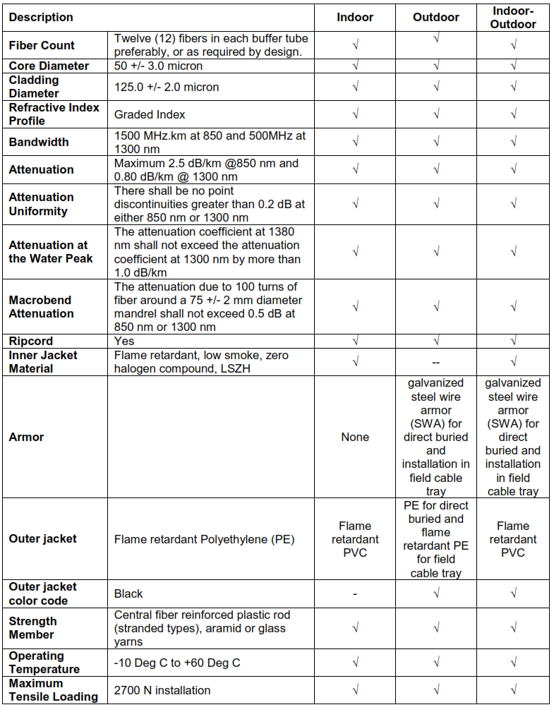
5.5. Multimode 62.5/125 µm
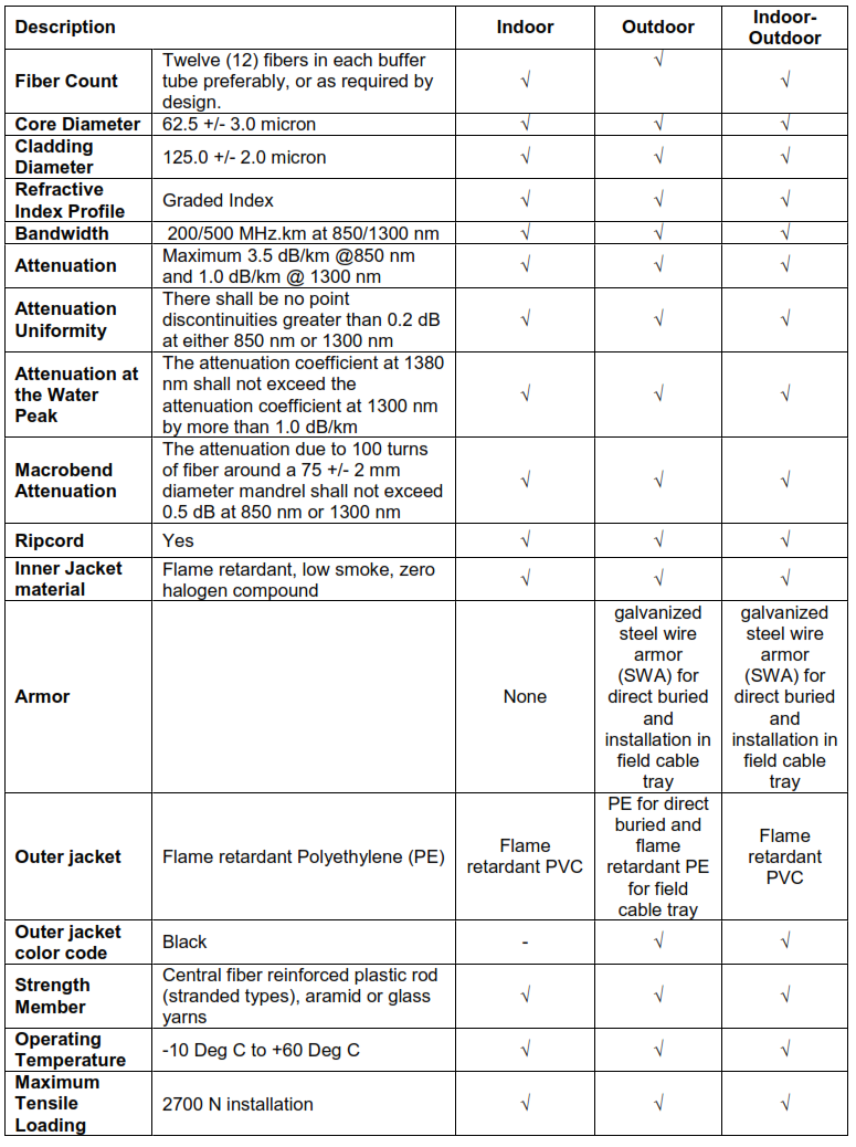
5.5.1. Multimode optical fiber characteristics shall comply with TIA-492AAAA-A, or IEC 60793-2.
5.5.2. Refer to the basic parameters of multimode fiber optic cable mentioned in the table 11.6.
5.6. Multimode 50/125 µm
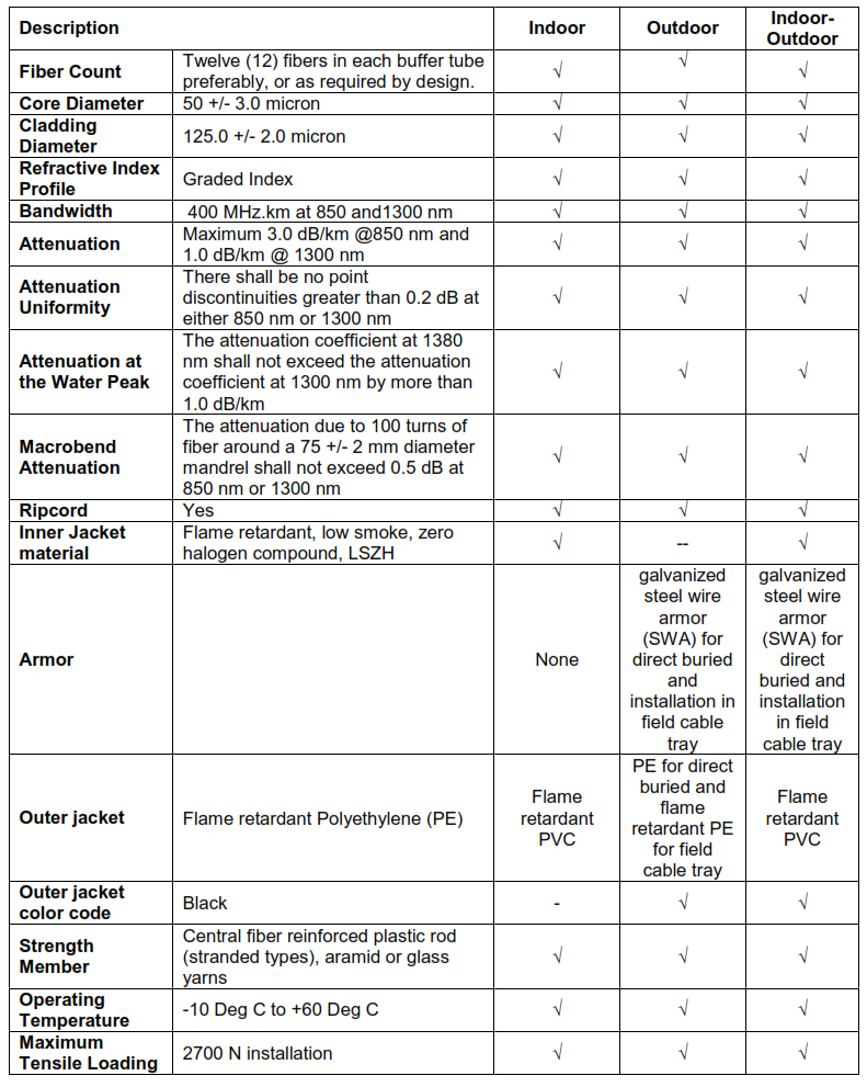
5.6.1. The multimode optical fiber shall meet EIA/TIA-492AAAB, or IEC 60793-2.
5.6.2. Refer to the basic parameters of multimode fiber optic cable mentioned in the table 11.7.
5.7. Laser Optimized multimode 50/125 µm
5.7.1. The standard laser optimized optical fiber specifications shall comply with TIA-492AAAC-A
or IEC 60793-2.
5.7.2. Refer to the basic parameters of multimode fiber optic cable mentioned in table 11.8.
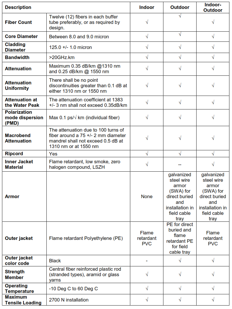
5.8. Single Mode
5.8.1. Single-mode fibers are typically used in long-distance applications, to support high
bandwidth applications. Single mode optical fiber shall meet the required minimum
specifications mentioned in TIA-4920000-B or IEC 60793-2.
5.8.2. The specification of single mode optical fiber to utilize for wavelengths of 1310nm and 1550
nm, shall comply with TIA-492CAAB.
5.8.3. Refer to the basic parameters of single mode fiber optic cable mentioned in the table 11.9.
6. 100 Ohm Category 6 Four Pair UTP Cables
6.1. General
6.1.1. For UTP cables used in IT services refer to SSITS-NSD-03 section 4.
6.1.2. Following shall apply to communication and control systems cables.
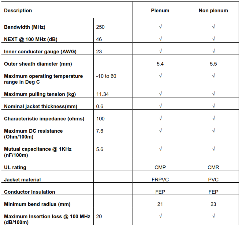
6.1.3. Category 6 designation applies to 100 Ohm balanced cables whose transmission
characteristics are specified up to 250 MHz bandwidth.
6.1.4. The cable shall consist of 22 AWG to 24 AWG thermoplastic insulated solid conductors
that are formed into four individually twisted pairs and enclosed by a thermoplastic jacket.
6.1.5. The physical design of cables shall meet the requirements of clauses 4.3.3.1 to 4.3.3.6 of
TIA /EIA-568-B.2.
6.1.6. The UTP cable shall meet or exceed the Category 6 transmission characteristics per
TIA/EIA-568-B.2-10
6.2. Basic Features
6.2.1. The cable shall have descending distance marking at every meter for cable length.
6.2.2. Matching tip and ring color code for ease of installation.
6.2.3. The UTP cable should have a rip cord to facilitate removal of the cable jacket.
6.3. Construction
6.3.1. The non-plenum version of the UTP cable shall be certified by ETL or equivalent, and UL
listed as type CMR.
6.3.2. The plenum version of the UTP cable shall be ETL Certified and UL listed as type CMP.
6.3.3. Color coding shall be done as per TIA/EIA-568-B.2.
6.3.4. Refer to table 11.11 for basic parameters of Category 6 UTP cable characteristics.
6.4. 100 Ohm Category 6 Four Pair UTP Patch Cord
6.4.1. Patch cords shall meet the following requirements:
a. Compatible with cross-connect system they are used for.
b. Backward compatible with Category 5 and Category 5e applications to match with
existing active equipment if any.
7. Coaxial Cables
7.1. General
7.1.1. Coaxial cable used as a transmission line for radio frequency signals, in applications such
as connecting radio transmitters and receivers with their antennas.
7.1.2. Coaxial cable has an inner conductor, surrounded by a tubular insulating layer of high
dielectric constant all of which are surrounded by a conductive layer and finally covered
with a thin insulating layer called jacket on the outside.
7.1.3. Coaxial cables used for radio communication system shall be designed and tested
according to the IEC 61196.
7.1.4. Refer to the radio equipment manufacturer’s recommended cables for optimum
performance of radio equipment.
7.2. Basic Features
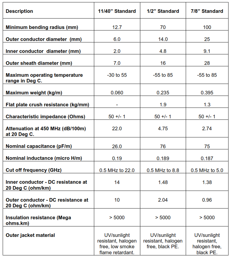
7.2.1. All coaxial cables used for radio communication shall have characteristic impedance of
50 ohms.
7.2.2. The inner conductor and the outer shield share the same geometric axis and shall have
uniform concentricity.
7.2.3. The jacket material shall be polyethylene (PE) and color shall be black, free from
imperfections to provide the cable with a tough and flexible, protection and able to
withstand the stresses expected in normal installation and service.
7.2.4. The outer jacket shall be UV/sunlight resistant made of PE tested according to
IEC60754.
7.2.5. Indoor cables shall be halogen free, low smoke, flame retardant and super flexible and
shall be tested as per IEC60754, IEC61034, IEC60332-1.
7.3. Construction
7.3.1. Dielectric type: Foam dielectric
7.3.2. Jacket material: Polyethylene (PE)
7.3.3. Jacket color: Black
7.3.4. Outer conductor material: Corrugated copper
7.3.5. Inner conductor material: Copper or copper-clad aluminum wire
7.3.6. The cable shall have low VSWR for the operating frequencies ranging from 400-450MHz.
7.3.7. Refer to table 11.12 for basic parameters of coaxial cable characteristics.
8. Inspection and Testing
8.1. General
8.1.1. Complete factory tests, in accordance with the requirements of the applicable standards
listed in Section 2.0 shall be performed.
8.1.2. Seller shall take SABIC approval for all routine tests to be performed and type of tests to
either be performed or certified. The listing shall specify the method and sampling. The
cables shall be shipped upon compliance of tests results with the requirements of this
8.1.3. SABIC reserves the right to witness all tests. The Seller shall provide written notification to
SABIC at least two weeks in advance of the test date. The notice shall include an outline of
the procedures used in performance of the tests.
8.2. Fiber Optic Cable
8.2.1. All optical fibers shall be 100 percent attenuation tested bi-directionally. The attenuation
shall be measured at 1310 nm and 1550 nm for single-mode fibers and for multimode
fibers, the attenuation shall be measured at 850 nm and 1300 nm as per TIA/EIA-455-B.
8.2.2. Optical Time Domain Reflectometer (OTDR) test to be carried out at site, test results to be
recorded and maintained. Cables shall be tested on the reel before installation and when
installed and terminated.
8.2.3. All fiber optic cables and optical fibers test procedures shall comply with relevant fiber optic
test procedures (FOTPs) in TIA/EIA-455-B and IEC 60793-1-1.
8.2.4. Fiber optic cables shall be UL listed for the applications as per the NEC Article 770.
8.2.5. Optical fiber non conductive riser cables shall pass requirements of UL 1666 for
flammability characteristics.
9. Identification and Tagging
9.1. Jacket for fiber optic cables
9.1.1. The following minimum information shall be printed on the jacket surface at every onemeter
intervals:
a. Sellers name or trademark
b. Date of manufacturer
c. Type of optical fiber
d. Number of fibers
e. Category of the cable
f. UL or other accredited testing laboratory label
9.2. Jacket for other cables
9.2.1. The following minimum information shall be printed on the jacket surface at every onemeter
intervals:
a. Sellers name or trademark
b. Date of manufacturer
c. Conductor size
d. Number of pairs/triad (fibers in fiber optic cables)
e. Voltage class (not applicable to fiber optic cables)
f. Temperature rating
g. UL or other accredited testing laboratory label
Specification.
10. Preparation for Shipment
10.1. Packing
10.1.1. Cables shall be shipped on non-returnable wooden reels. The vendor shall indicate in his
proposal the maximum reel size and longest possible shipping length for each size of
cable. SABIC shall specify shipment in cut lengths or bulk standardized reel lengths.
Cable length tolerance shall be +/- 3 percent of the specified length.
10.1.2. Cable ends shall be sealed using heat shrinkable, self-sealing end caps to prevent the
entrance of moisture into the cable prior to installation. Cable ends shall be secured to
reel in such a way that no damage to the wire is incurred. Nailing or stapling of cable to
side reel is not acceptable. Both ends shall be available for testing while the cable is on
the reel without removing the cable reel impact protection.
10.1.3. Impact protection for cable on each reel shall be provided by wood lagging over the
circumference of the reel.
10.2. Reels for fiber optic cables
10.2.1. A weatherproof metal tag suitable for 2 years of outdoor storage shall be affixed to each
wooden reel, visible without removal of packing material, with the following information:
a. Buyer’s purchase order number
b. Buyer’s item code number
c. Buyer’s reel number
d. Seller’s Name or Trademark
e. Date of manufacturer
f. Type of optical fiber
g. Number of fibers
h. Category of the cable
i. Number of optical fibers
j. Length of cable on reel
10.3. Reels for other cables
10.3.1. A weatherproof metal tag suitable for 2 years of outdoor storage shall be affixed to each
wooden reel, visible without removal of packing material, with the following information:
a. Buyer’s purchase order number
b. Buyer’s item code number
c. Buyer’s reel number
d. Seller’s Name or Trademark
e. Date of manufacturer
f. Conductor size
g. Number of pairs/triad in cable
h. Voltage class
i. Temperature rating
j. Length of cable on reel
10.4. UTP Cables
10.4.1. Shall be available in Spool-in-Box packaging suitable for indoor storage with the following
information:
a. Buyer’s purchase order number
b. Seller’s Name or Trademark
c. Conductor size
d. Number of pairs/triad in cable
12. Cable Specification Tables
12.1. ANALOG SIGNAL CABLES
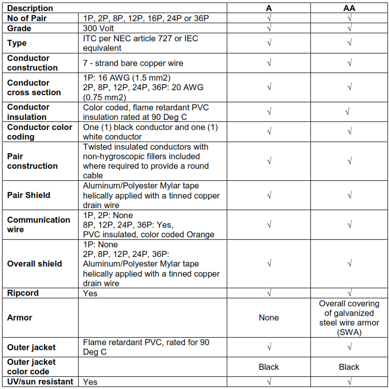
Note: In addition to above, Intrinsically Safe Cables type AI and AIA shall conform to IS requirement
per NEC Article 504 or IEC equivalent. The overall jacket color shall be light blue.
12.2. DIGITAL SIGNAL CABLES
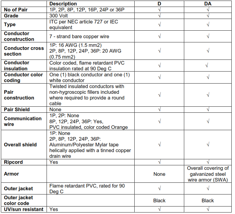
Note: In addition to above, Intrinsically Safe Cables type DI and DIA shall conform to IS requirement
per NEC Article 504 or IEC equivalent. The overall jacket color shall be light blue.
12.3. TRIAD SIGNAL CABLES
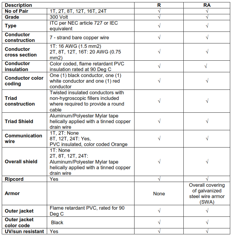
Note: In addition to above, Intrinsically Safe Cables type RI and RIA shall conform to IS requirement
per NEC Article 504 or IEC equivalent. The overall jacket color shall be light blue.
12.4. TYPE KX (CHROMEL/ALUMEL) THERMOCOUPLE EXTENSION CABLES
12.5. TYPE TX (COPPER/CONSTANTAN) THERMOCOUPLE EXTENSION CABLE
12.6. FIBER OPTIC MULTIMODE CABLES 62.5/125
12.7. FIBER OPTIC MULTIMODE CABLE 50/125
12.8. LASER OPTIMIZED FIBER OPTIC MULTIMODE CABLE 50/125
12.9. FIBER OPTIC SINGLE MODE SIGNAL CABLES
12.10. FOUNDATION FIELDBUS SIGNAL CABLES (TRUNK and SPUR CABLES)
12.11. 100 Ohm CAT6 UTP CABLE
12.12. COAXIAL CABLE