1. SCOPE …………………………………………1.1 Scraper
Trap
1.2 Piping
2. REFERENCES ………………………………3. DEFINITIONS
4. GENERAL REQUIREMENTS
4.1 Trap
…………………………………………
4.2
Layout of Associated Piping
4.3
Typical
Drawings
5. SCRAPER TRAPS …………………………
5.1
Purchase Order Information
5.2 Design
5.3 Trap Components
……………………..
5.4 Branch
Connections
5.5 Flanges
5.6 Quick Opening Closures ……………5.7
Supports
5.8
Material
5.9 Fabrication
……………………………….
5.10 Quality Requirements
5.11 Documentation
………………………….
5.12 Marking
5.13 Scraper Passage
Indicators
5.14 Scraper Handling Equipment ……..6. SCRAPER PIPING
6.1 Piping
6.2
System Design ………………………….
6.3
Valves
6.4
Barred
Tees
6.5 Bends
………………………………………
6.6
Station
Layout
6.7
Small
Fittings
6.8
Fabrication and Erection ……………
1. Scope
1.1 Scraper Trap
1.1.1 Scraper Traps
This specification defines the minimum requirements governing the design, fabrication of permanent
scraper traps
1.1.2 Size Limitation
The traps shall be limited to a minimum line size of NPS 4.
1.1.3 Pressure Class
The pressure class shall be limited to ASME classes 150 through 1500.
1.1.4 Use
The scraper traps covered by this standard include the whole range of devices. The traps may be used for
launching, or receiving, or both. Scrapers may be for cleaning, separation of fluids or batches, and various
processes, such as inspection, and maintenance.
1.1.5 Limits
The trap assembly is limited to the mating flanges.
1.2 Piping
This standard defines the minimum requirements governing the design of piping and appurtenances for
permanent pipeline scraper launching and receiving stations.
1.2.1 Codes
This standard supplements ASME B.31.3, ASME B31.4, and ASME B31.8 codes for pressure piping and
design requirements, and includes the design of the piping associated with the trap.
1.2.2 Exclusions
This standard does not apply to special valves which can be used to launch or receive small size scrapers.
These valves are specified, when necessary, by means of a duty specification. This type of valve may,
however, be included in typical drawings.
2. References
All referenced specifications, standards, codes, forms, drawings and similar material, including all
revisions, addenda and supplements, shall be of the latest issue unless stated otherwise. When a project
is in effect, the version of engineering and design codes, specifically ASME B31 codes, shall govern, as
specified in the contract for that project.
SABIC Engineering Standards (SES)
P16-G01 Butt-Welding Pipe Fittings
American Petroleum Institute (API)
5L Specification for Line Pipe
American Society of Mechanical Engineers (ASME)
B16.5 Pipe Flanges and Flanged Fittings
B16.9 Steel Buttwelding Fittings
B31.3 Process Piping
B31.4 Liquid Transportation Systems for Hydrocarbons, Liquid Petroleum Gas, Anhydrous Ammonia,
and Alcohols
B31.8 Gas Transmission and Distribution Piping Systems
Section VIII Boiler and Pressure Vessel Code, Div. 1, Pressure Vessels
American Society for Testing and Materials (ASTM)
A 36 Carbon Structural Steel
A 216 Steel Castings, Carbon, Suitable for Fusion Welding, for High Temperature Service
A 515 Pressure Vessel Plates, Carbon Steel, for Intermediate- and High-Temperature Service
A 516 Pressure Vessel Plates, Carbon Steel, for Moderate- and High-Temperature Service
A 537 Pressure Vessel Plates, Heat Treated. Carbon Manganese-Silicon Steel
A 662 Pressure Vessel Plates, Carbon- Manganese, for Moderate and Lower Temperature Service
Manufacturers Standardization Society (MSS)
SP-75 High Test Wrought Welding Fittings
National Association of Corrosion Engineers (NACE)
MR0175 Material Requirements-Sulfide Stress Cracking Resistant Metallic Material For Oil Field
Equipment
3. Definitions
For the purpose of understanding this standard, the following definitions apply.
Scraper. The term “scraper” includes all devices that are placed in a pipeline to move through the line. The
purpose for moving through the line includes, but is not limited to internal cleaning, gauging, inspection,
and batching.
Trap. The term “trap” refers to the devices used for launching or receiving the scrapers.
MTR. Material Test Report
SPI. Scraper passage Indicator
4. General Requirements
This standard is structured in two parts.
4.1 Trap
The first section covers the requirements leading to a purchase order for the trap to be purchased from a
fabricator.
4.2 Layout of Associated Piping
The second section covers the typical piping associated with the launcher – receiver.
4.3 Typical Drawings
The typical drawings show the piping, and suggest the standard orientation of the nozzles, as well as taps
for venting, draining, and instrumentation.
5. Scraper Traps
5.1 Purchase Order Information
The Purchase Order shall include all applicable drawings necessary to correctly define the items, and all
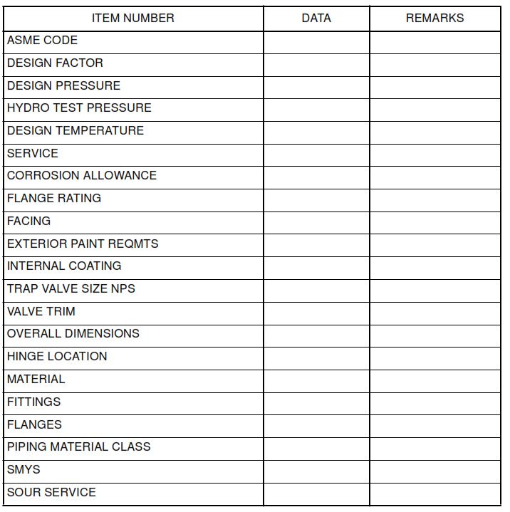
Data Sheets for the equipment. A sample Data Sheet is located at the end of this standard.
5.2 Design
5.2.1 General
Scraper traps are generally located inside the plant area limit but are considered as the termination of the
pipeline, and therefore within the scope of the same piping code as the pipeline.
5.2.2 Design Calculations
The design calculations for the trap, shall be made with the same design data as the accompanying
pipeline. All branch connections shall be fully reinforced. The corrosion allowance for the trap, shall be no
less than that of the pipeline. The corrosion allowance is listed on the Data Sheet, and shall be approved
by the project metallurgist.
5.2.3 Dimensions
a. The overall dimensions for scraper traps shall be in accordance with the Data Sheet.
b. Bi-directional traps shall permit launching of one scraper and receiving two scrapers with the
maximum length of the scraper type, excluding instruments scrapers, to be used.
5.2.4 Size Relationship
The nominal size of the barrel shall normally be 2 pipe sizes larger than the line for pipelines up to NPS 10,
4 pipe sizes larger for pipelines NPS 12 to 28, and 6 line sizes larger for pipelines NPS 30 and larger.
5.2.5 Proportions
a. The length of the smaller diameter portion shall be sufficient to permit installation of the required
piping connections and not less than the maximum scraper length.
b. The scraper passage indicator on receivers shall be located at 150 mm upstream of the reducer.
c. The distance from the centerline of the kicker line to the attachment weld of the closure door
collar shall not exceed one trap diameter.
5.3 Trap Components
5.3.1 Cylindrical Sections
Cylindrical sections, or the “body”, shall be made from seamless or welded pipe or from rolled and seam
welded plate.
5.3.2 Reducers
a. The wall thickness of reducers shall be equal or greater than matching pipe, at the large end.
The material shall be of equal strength.
b. Concentric and eccentric reducers shall be ASME B16.9 type. Conical reducers may be used if
the apex angle does not exceed 12 degrees. The diameters of the reducer and the matching pipe
sections shall be within the tolerance prescribed in the governing code.
c. Reducers that are not listed in ASME B16.9 or MSS-SP-75 shall be designed in accordance with
ASME B31.3.
5.4 Branch Connections
5.4.1 Branch Type
Branch connections may be made by welding, or extrusion.
5.4.2 Reinforcement
All welded branches shall be reinforced, either by an integrally forged outlet fitting, or a reinforcing pad.
5.4.3 Reinforcing Pads
Reinforcing pads, when used, shall be fully welded and shall be provided with a 6 mm vent hole. The
tapped hole shall be filled with heavy grease.
5.5 Flanges
Flanges shall be weld neck type. Flange rating and facing is specified on the Data Sheet.
5.6 Quick Opening Closures
5.6.1 Closure Requirements
All traps shall be built with quick opening end closures. The closures shall be of a design that will allow one
man operation for both opening and closing. The closure shall be in accordance with the requirements of
ASME Boiler and Pressure Vessel Code, Section VIII, Div. 1, paragraph UG-35.
5.6.2 Locking Mechanism
The locking mechanism of the closure shall be limited to the clamp-ring, band lock or threaded type. All
other types of locking mechanisms shall be submitted for approval in the vendor’s quotation. The C-clamp
type with bolt tightening from both sides of the door is not permitted. Threaded type closures are limited to
trap size of NPS 24 or smaller.
5.6.3 Closure Doors
All closure doors shall be operated with adjustable hinges or an adjustable davit. The direction of view for
determination of the hinge position for horizontal traps is from the closure end of the trap. The hinge
position shall be on the left-hand side, as viewed from the closure end of the trap.
5.6.4 Door Clearance
The Vendor shall indicate the required clearance area for the door, on the approved drawing.
5.6.5 Lubrication Requirements
Lubrication injection nipples shall be provided where large friction areas are present, on threaded type
closures
5.6.6 Maintenance
All closures shall require no maintenance other than lubrication of seals.
5.6.7 Closure Seals
a. The closure seals shall be Chevron type or self-energizing seal type.
b. O-ring seals must have a groove configuration or other design features that will prevent slippage
of the O-ring during the door closure.
c. Vendor shall specify the seal type, dimensions and material at time of quotation.
5.6.9 Special Tooling
The closures for large size traps may require additional tooling to assist the operator in breaking and
compressing the seal, when opening and closing the door. All required tooling, and devices shall be noted
in the proposal, and included in the package delivered. The closure shall include appropriate storage for
any tooling.
5.6.10 Closure Safety
An interlock system shall be fitted to the closure mechanism. The interlock shall ensure that the door
cannot be opened while pressurized, and that the door will not close without the interlock being engaged.
When the fluid is sour or toxic, any fluid released while depressurizing, shall be piped to a safe location.
5.7 Supports
5.7.1 General
The supports used for horizontal scraper traps shall be designed for sliding motion. All dimensions for the
supports shall be included in the proposal, as well as the final package.
5.7.2 Support Design
The supports shall be designed with a vertical load of twice the mass of the trap filled with water, and an
axial load of twice the mass of the of the trap filled with water adjusted for the friction factor. When steel is
used, the factor is 0.5. When low friction, non-corrosive sliding material is used, the design shall prevent
the entry of sand that will alter the friction factor.
5.8 Material
5.8.1 General
a. All materials shall conform to the requirements of the applicable code and shall be traceable to
mill certificates.
b. Specific materials are specified on the Data Sheet. The use of used or reclaimed materials or
materials of unknown specification are prohibited.
c. Copies of MTR’s shall be provided.
5.8.2 Acceptable Carbon Steel Material
The following materials are listed as acceptable, and do not abrogate the information specified on the Data
Sheet.
a. When carbon steel is specified, the pipe material shall be seamless or SAW pipe, API 5L Grade
B through X60, or ASTM A106 Grade B.
b. Plate materials used for pressure containing parts shall be as a substitute for pipe include:
ASTM A515, A516, A537 CL1, A537 CL2, or A662.
5.8.3 Acceptable Carbon Steel Materials for Sour service
a. Pipe material used for sour service shall be in accordance with NACE MR0175.
b. Plate materials used for pressure containing parts shall be ASTM A516, A537 CL1, A537 CL2 or
A662, as well as NACE MR 0175.
5.8.4 Sour Service
When the Data Sheet indicates sour service, all pipe and fittings, including flanges shall be in accordance
with NACE MR0175.
5.8.5 Castings
Carbon steel castings shall be in accordance with ASTM A216 grade WCB.
5.8.6 Structural Steel
Structural steel used for non pressure containing parts shall be in accordance with ASTM A36, S-1 or
better.
5.9 Fabrication
5.9.1 Bolt Holes
Flange bolt holes shall straddle the vertical and horizontal centerlines unless orientation is given on the
scraper trap drawing.
5.9.2 Welding and Heat Treatment
Welding shall be in accordance with the appropriate ASME code.
5.10 Quality Requirements
5.10.1 Quality Program
The Vendor shall maintain a Quality Program. The program shall be available for SABIC approval.
5.10.2 Shop Inspection
The items manufactured to this standard are subject to inspection by SABIC.
5.10.3 Inspection and Acceptance
a. All butt welds shall be 100% radiographed in accordance with the requirements of ASME BPV,
Section VIII, Division 1, Appendix 4.
b. All full penetration groove welds shall be inspected by magnetic particle testing in accordance
with the requirements of ASME BPV, Section III, Division 1, Appendix 6.
5.10.4 Hydrostatic Test
The hydrostatic pressure test shall be applied for not less than one hour. The pressure shall produce a
hoop stress of 90% of SMYS in the shell, or a test at the hydrostatic shell test, as specified in ASME
B16.5, whichever is lower.
5.11 Documentation
5.11.1 Calculations and Drawings
The Vendor shall submit 3 sets of calculations and drawings to the Buyer for approval at least 4 weeks prior
to start of fabrication of the scraper traps.
5.11.2 Final Documents
The Purchase Order shall specify, the following final documents. The Vendor shall provide to the Buyer as
part of the order three copies of the following documents.
a. Certified Drawing(s)
b. Calculations
c. Hydrotest certificate
d. Spare Parts List
e. Welding procedures
f. NDE records including hardness testing
g. Heat treatment records
5.12 Marking
5.12.1 Manufacturer’s Nameplate
A nameplate, made of 1.5 mm minimum thickness, stainless steel or monel shall be attached to each trap.
The plate shall be attached securely on a support that is continuously welded to the scraper trap, with
stainless steel or monel fasteners.
The plate shall be located so that the nameplate data can be read from the normal position near the
closure. The nameplate shall be marked by raised letters or by die stamping.
The nameplate shall include the manufacturer’s name and location, Purchase Order number, serial
number, maximum allowable operating pressure, sour or non-sour service, hydrostatic test pressure,
design code, date of manufacture, and empty weight, as a minimum.
5.13 Scraper Passage Indicators
Scraper passage indicators (SPI) shall be bi-directional. The indicators shall give positive indication of
scraper passage. The indicators shall not solely be dependent on a painted marking or other method that
can become obliterated. The indicators shall be designed for manual reset. The indicators shall allow
replacement of all moving parts with pressure in the line. When scraper passage indicators are installed on
a buried portion of the pipeline, they shall have an extended stem, with NPS 4 pipe protective sleeve. The
extension shall place the dial or pointer will be approximately 50 cm above ground.
5.14 Scraper Handling Equipment
When scraper stations are used on lines larger than NPS 16, a mechanical scraper loading device with
suitable lift and span shall be provided. The device is used to assist in the loading and the receiving of
normal cleaning and batching scrapers. The lifting capacity shall be a minimum 900 kg for line sizes up to
NPS 36 and a minimum of 1800 kg for larger diameter lines.
6. Scraper Piping
6.1 Piping
6.1.1 P&I Diagram
Permanent scraper traps shall be installed on the pipeline as indicated on the P&I drawings.
6.1.2 Philosophy
Scraper trap stations shall be designed to operate with a minimum of flow disruption. The flow rate during
operation shall correspond to the maximum recommended scraper velocity, unless the fluid immediately preceding the scraper must be diverted to a side stream. The pipeline system shall be designed to provide
control the velocity of the scraper at all times. The system must be designed to receive and dispose of
liquid slugs as well as the any solids brought in by the scraper, if required.
6.1.3 Basic Design
Scraper trap stations shall be designed for bi-directional scraping when permanent facilities exist for
pumping in either direction. Bi-directional design is also appropriate when sources of test water, and a
disposal site is at both ends.
6.2 System Design
The design for scraper trap station piping shall be in accordance with the attached typical drawing. The
following is a description of the components.
6.2.1 Trap Isolation Valve
The trap isolation valve must be the same size as the pipeline, and be full bore.
6.2.2 Mainline Tee
A barred tee shall be placed in the mainline.
6.2.3 Distance from the Branch
The distance between the centerline of the branch and the near end of the trap isolation valve shall be
kept to a minimum. When the distance is more than three pipe diameters, the line shall be sloped back to
the branch.
6.2.4 Tieline
A tieline valve shall be placed at the branch of the tee at the minimum practical distance from the mainline.
6.2.5 Bypass Line
A bypass line shall run between the tieline valve and the trap. The bypass line contains a kicker valve and
a second block valve to provide tight shut-off in the bypass line.
6.2.6 Equalizing Line
A small size equalizing line with locked open block valve shall be provided to connect the small diameter
end of the trap with the other end to prevent unwanted pressure differential when a scraper seals off the
narrow part of the trap. The equalizing valves shall be capable of for throttling and tight shut off.
6.2.7 Test Water Valve
A blinded valve is provided for test water.
6.2.8 Drain
A double valved drain system shall be provided on the shell that is sized to accommodate drainage of the
trap within approximately 15 minutes. A check valve shall be installed if back flow from the disposal
system can occur.
6.2.9 Vent System
There shall be a vent system to route gas and vapors to a safe location before the trap closure is opened.
Sour gas and liquids shall be piped to a suitable location for subsequent disposal. Sweet gas and sour
vapors from liquid crude or water may be vented to atmosphere at a safe location not less than 6 m above
grade near the trap.
6.2.10 Purge Connection
A purge connection shall be provided on all traps, as indicated on the P&ID.
6.2.11 Sample Connection
A sample connection shall be installed at the bottom of the scraper receiver when a valved connection for
the injection of chemicals at launching stations is required.
6.2.12 Pressure Gauges
Two pressure gauges shall be provided, one near the trap closure, and one on the mainline near the trap
isolation valve.
6.2.13 Scraper Passage Indicators
Scraper passage indicators shall be placed on the mainline, one scraper length downstream and beyond
the barred tee on each launcher, and near the small diameter side of the reducer on each receiver,
6.2.14 Restrictions
A pipeline, that is intended to carry scrapers, shall not have any valves, fittings or connections that may
impede the travel of the scraper.
6.3 Valves
6.3.1 Valve Types
Generally, the correct valves are in the associated Material Class.
6.3.2 Power Operators
All valves with powered actuator shall be provided with a manual override. Powered actuators, shall permit
operating personnel to stop the valve stroke and reverse the stroke at any point of the stroke.
6.4 Barred Tees
All tees and other branch connections in the pipeline equipped with permanent scraping facilities shall
allow the free passage scrapers. The type of scrapers that must pass include sphere scrapers, scrapers
with cups or discs and with OD without gauging plates, and instrumented scrapers. When the branch bore
exceeds 60 percent of the run bore, the branch shall be provided with guide bars. Bars are also required for
branch pipe sizes of NPS 6 and larger, if cleaning scrapers with spring mounted brushes will be used.
6.5 Bends
6.5.1 Long Radius Bends
Long radius bends shall be used in pipelines with permanent scraping facilities.
6.5.2 8D Bends
The minimum bend radius shall be eight diameters (8D) for lines up to NPS 8.
6.5.3 5D Bends
The minimum bend radius shall be five diameters (5D) for lines NPS 10 through NPS 14.
6.5.4 3D Bends
The minimum preferred bend radius shall be five diameters (5D) for lines NPS 16 and larger. Three
diameter bends (3D), may be used in these sizes when 5D bends cannot be used because of space
limitation, or difficulty in procurement, subject to review and approval.
6.6 Station Layout
6.6.1 Placement
When scraper traps are provided at the ends of pipelines near a plant area, they shall be in a scraper trap
area inside of the plant. The piping between trap and plant shall be constructed above grade.
6.6.2 Clearance
Scraper traps for pipelines in hydrocarbon service shall be not less than 45 m from plant equipment or
piping, when measured from the closure door.
6.6.3 Platforms
Platforms shall be provided as necessary, and subject to approval, for easy access to valve actuators and
closure operating mechanism. All valves shall be accessible from one side of the trap.
6.6.4 Working Space
A suitable working space shall be provided with sufficient room around the traps for loading and unloading
scrapers. Access by moving equipment such as a fork lift truck, shall be provided. The clearance between
the bottom of the trap and finished grade shall be approximately 1 m. A surface drainage system shall be
provided to collect all spills and wash water.
6.6.5 Trap Abovegrade Piping
At piping that cross connects the upstream and downstream pipelines, and associated kicker and
equalizer lines shall be constructed above grade.
6.7 Small Fittings
Threaded or socket welded fittings shall be class 3000 rating for pipewalls extra strong (XS) and less, and
class 6000 rating for lines for pipewalls above XS.
6.8 Fabrication and Erection
Threaded branch piping shall be seal welded up to the first valve. The seal weld shall cover all exposed
threads that remain after the joint has been tightened to full thread engagement. The seal weld shall have
a minimum throat thickness of 2 mm. The weld shall merge smoothly into the pipe metal outside of the
thread. PTFE (Teflon) tape or joint compound shall not be used in threaded joints that will subsequently be
seal welded.
Data Sheet