Instrument Technician Using PPE (Personal Protective Equipment)
Safety Document
Maintenance Work Permits. & SCC (Safety Clearance Certificate) If Required
Tools/ Special
I &C Tool Kit & special tools (if Required)
Test Equipment
Tools
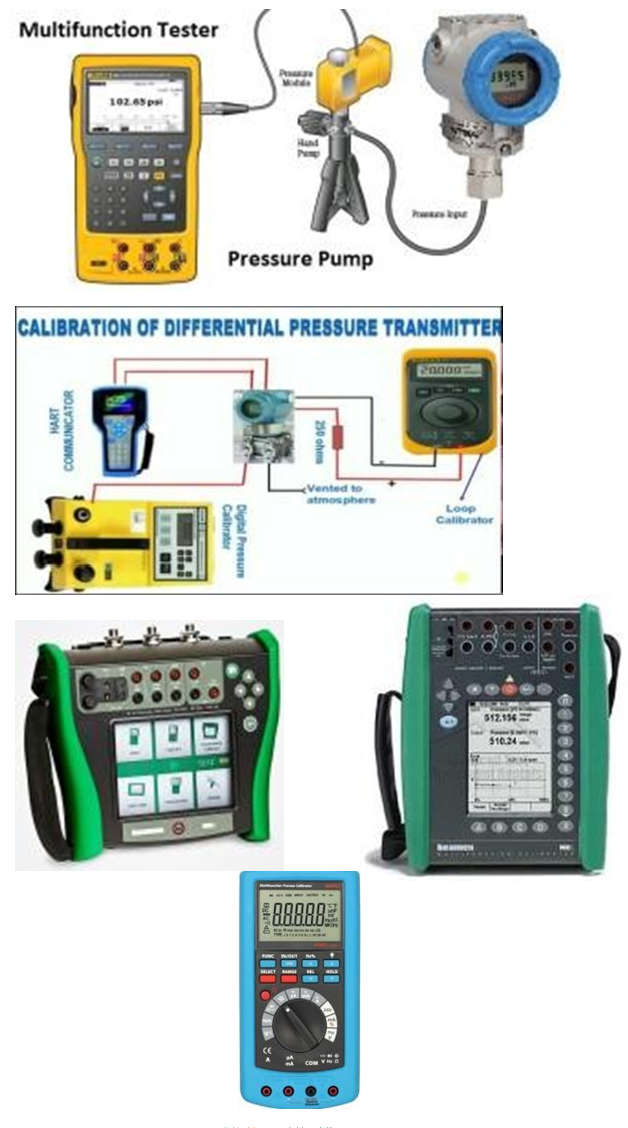
Test Equipment:
Note: Select test equipment according to the max. Range & Medium.1– Digital multi-meter / mA meter / SMART HART Calibrator
2– Deadweight Tester, Standard Pressure Gauge (0.5 Bar to 200 Bars)
3– Hydraulic pressure pump and standard pressure gauge (0 Bar to 250 Bars). 4– Air pressure pump with digital multifunction calibrator used for very low and low pressure (0 to 20000mmH2O or 0to 2 Bar or 0 to 20 Bars). 5– Water manometer or mercury manometer with air pump (0 to 1500 mm H2O or 0 to 1500mmHg).
6- Vacuum pump with digital multifunction
tester.(0 to -760 mmHg / 0 to -30 inches Hg or 0 to -1 Bar)
Stores &
Cleaning spray, brush and cloth
Materials
Job Description
Process
Steps
During Maintenance
Isolation& Removal
1
Isolate the transmitter by closing inlet valve of many fold or isolate from the main isolating valves of impulse lines.
2
In case of oil or chemical process use secondary container to avoid spill of oil / chemical when isolating. Depressurize the transmitter and draining tapping lines.
3
Confirm that power supply is OFF. Remove the wires from the transmitter terminal by the core identification and insulate all wires terminals by insulation tape (Ensure it isn’t in contact with each other, short circuiting or producing any earth).
4
Move away the tapping lines to avoid spill of oil or chemical from transmitter connections. Disconnect the SMART pressure transmitter or differential pressure transmitter form the process carefully.
5
Carry out the Pressure transmitter / diff. pressure transmitter external cleaning, using a brush and approved Cleaning spray to remove contamination or solid particles.
6
Inspect the Pressure or Diff. Pressure Transmitter for external physical damage, general appearance & fitness. (Check whether cover seals are intact).
Preparation
7
Write all the details of pressure transmitter: tag no., range, service and unit no. in the calibration sheet.
8
Damping of Transmitter: Many hart transmitter supports a function Damping. Damping means a delay between change in the transmitter inputs and detection of change in digital value for transmitter input reading and corresponding to the output values. It is better to adjust the transmitter damping value at zero before performing test. After test re-adjust the original value of damping before installing in field.
9
Collect the configurations values & calibration range from Engineer of each transmitter (millimeter WC till maximum range in bars) and note in the calibration sheet.
10
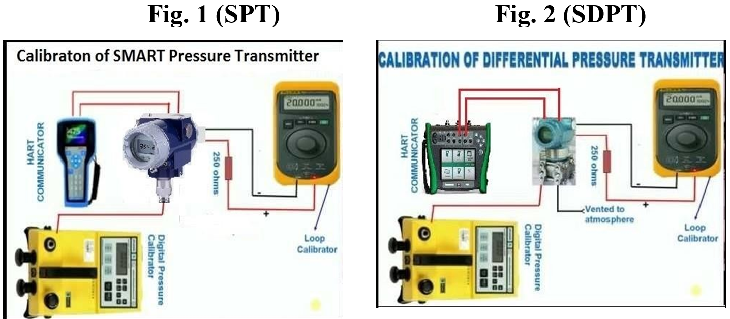
Set up the test equipment as shown in the diagram:
11
Ensure that the medium used for calibration is same as that of medium of the process (If possible) in witch transmitter is installed.
12
Carry out purging (if required) to remove the process medium completely from the transmitter internals (Pressurize, Fill & Drain).
13
Carry out the leak test by applying the pressure, to the transmitter & check for leakages. (Pressurize at full scale and wait for at least one minute). If there is any leakage in connections, tighten. Note:1– Always use High pressure port of Diff. pressure transmitter and keep
Low pressure port free in air for reference. 2- Never apply pressure more than the rated pressure; otherwise pressure sensor of transmitter will be damaged.
14
Connect multi-function HART communicator as shown in diagram and
VIP
switch ON and wait for stabilize. Before start calibration, check configuration & confirms all parameters, (If required) which are supplied by Engineer by SMART calibrator. {Like: tag no, service name, process name, (pressure, level or flow), engineering units, in case of flow
check square root extractor for local indication, input minimum and
maximum ranges, output current range set on 4~20mADC, Damping values, burn out at LRV & URV, date of calibration, next time schedule for calibration, etc.}
15
Exercise the pressure element to stretch for full range and back to zero to make sure that element can operate normal.
Calibration
16
A procedure of digital calibrating of a SMART transmitter is called Digital Trimming. A digital trimming is an exercise that allows you to correct the transmitter digital signal to match with plant standard (input pressure range and output digital mA). Digital trim of smart transmitter can be done in 2 ways. (As shown in step 22)
17
Without apply actual pressure, apply 0% input pressure on the SMART communicator & wait to establish the output by the SMART transmitter till it reaches 4.0 mA on the SMART HART communicator & note the digital 4mA in the calibration sheet.
18
Without apply actual pressure, Now apply 100% pressure on the SMART communicator according to range provided by Engineer and wait to establish the digital output 20.0mA by the SMART Transmitter on the SMART HART communicator & note the digital 20mA in the calibration sheet.
19
If outputs of the above both value are correct then check middle 3 points by applying pressure from the HART Communicator and wait to establish output on the HART communicator. (At 25% input pressure, digital output = 8mA, at 50% input pressure, digital output =12mA and at 75% input pressure, digital output=16mA) for rising and falling values. Note these values in the calibration sheet.
20
Record these input/output values in the calibration sheet as found column or before calibration column.
21
If all reading are correct and error is in limit or below of the design values then record these values in as found column or before calibration column and go to step 42.
22
If deviation (error) is more or less than designed error and instrument is not passed by HART Communicator then adjustment is required. This adjustment is called trimming. There are 2 types of trimming. (1) Sensor trimming & (2) 4-20mA trimming
23
1st way of trimming is Sensor trimming. Start HART communicator & go to options. Select the proper option.
24
Performing a Sensor trimming: For sensor trimming we should follow the SMART communicator manufacturer procedure as mentioned in there manual. Normal guide lines are as follows.
25
Apply 0% pressure (“low” range value) by the SMART communicator, stimulus to the transmitter and wait for stabilize.
26
Execute 0% sensor (“low” sensor) trim function according to the SMART communicator manufacturer’s procedure.
27
Apply 100% Pressure (“high” range value) stimulus to the transmitter and wait for stabilize.
28
Execute 100% (“high”) sensor trim function according to the SMART communicator manufacturer’s procedure.
29
2nd way of trimming is 4~20mA trimming. Start HART communicator & go to options. Select the proper option.
30
Performing 4-20mA Trim. For 4~20mA trimming we should follow the SMART communicator manufacturer procedure as mentioned in there manual. General guide lines performing 4mA & 20mA Trimming.
31
Using hand held HART communicator; put transmitter output into fixed current mode. The input value for this test is mA asked to produce by the transmitter. The output value can be measured by precision mA meter. Calculate the error between digital mA (PVAO) and produced by transmitter and analog mA on the precision mA meter. If the test does not pass and deviation is more than the designed error then follows the Manufacturer’s recommended procedure for trimming the output. This procedure requires 2 trim points 4mA and 20 mA.
32
Execute 0% (“low “) output “4mA” trim test function on the transmitter.
33
After stabilizing 4mA on the HART communicator, measure the output signal 4mADC on the precision or digital Amp. Meters.
34
Execute 100% “High “output “20mA” trim test function on the transmitter.
35
After stabilizing 20mA on the HART communicator, measure the output signal 20mADC on the precision or digital Amp. Meters.
36
Enter / save these measured current values when prompt by transmitter.
37
Once the trim procedure is completed, calibrate according the standard values known to be accurate. Set lower and upper ranges. Note: The only reason for trimming a SMART transmitter is to ensure accuracy over the long period of time.
38
After completion of both trim tests, next step is the actual calibration by giving actual input pressure 0% to 100% and measure the 4~20mADC of all 5 points on the mA meter.
39
Check repeatability by increasing and decreasing pressure and confirm all 5 points (0%, 25%, 50%, 75%, & 100%) proportional to output values and match with standard values. Calculate the error in %, it should be within range of designed error.
40
Record the all values in the calibrations sheet in after calibration column.
41
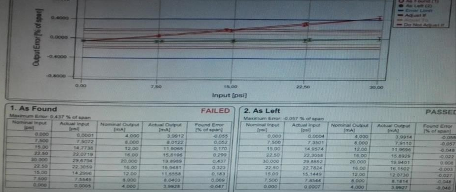
Documented calibration throughout the HART communicator before and after calibration, in such way communicator gives us complete result before and after calibration with the error calculation and can print result for us. These results can be shown like this chart.
42
The SMART pressure transmitter or SMART diff. pressure transmitter trimming procures and input / output values should be inspected by Inspector and Quality Inspector for witness and record these values to sign the certificate after completion of job.
43
After test re-adjust the original value of damping by the SMART communicator before installing in field.
44
It is necessary to adjust head correction (If any) to avoid any wrong reading.
Completion
45
Once the test is completed, remove the test equipment and clean the tested device.
46
Install the SMART transmitter back to its position and reconnect the instrument fittings, tubing without bending or damaging and ensure that connector is not cross fitted that can damage threading.
47
Close the drain valve and open the inlet valve slowly to avoid sudden pressure entering in the transmitter sensor.
48
In case of water / oil / chemicals, purge the air completely from the transmitters, tube lines / capillary tube, fill the transmitter carefully to avoid showing any wrong readings.
49
Check for leakage during commissioning.
50
Complete the check and calibration sheet and handover to the concerned I&C Engineer for inspection and signature