Analog, Digital Indicator & Recorder Calibration Procedure
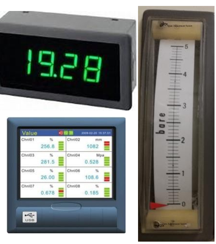
1- Analog Indicator (AI)
2- Digital Indicator (DI) (Input: 4~20mADC)
3- Digital single channel / multi-channel Recorders (DR) (input: 1~5VDC) (Pressure, Temperature, level, Flow& Valve position Indicator)
Procedure
General Procedure for all stations.
Title of Job
Maintenance Check & Calibration
Manpower
Instrument Technician Using PPE (Personal Protective Equipment)
Safety Document
Maintenance Work Permits. & SCC (Safety Clearance Certificate) If Required
Tools / Special
I &C Tool Kit
Test Equipment
Tools
Test Equipment:
Note: Select test equipment according to the Indicator / Recorder.
4~20 mADC Source 1~5VDC
1- DC 4~20mA Source 2- DC 1~5 volt Source 3- HART Communicator 4- Crocodile lead wires.
Stores &Materials
Cleaning spray, brush and cloth
Job Description
Process
Steps
During Maintenance
Isolation& Removal
1
Open the back cover of Indicator or recorder to gain access to the wires. Remove the wires by the core identification and insulate all wires by insulation tape (Ensure it isn’t in contact with each other, short circuiting or producing any earth). Note: These types of AI, DI & DR can be calibrated at their own locations. It is not necessary to remove.
2
Carry out the external cleaning, using a brush and approved cleaning spray to remove dust, contamination or solid particles.
3
Inspect for external physical damage, general appearance & fitness.
Preparation
4
Write the all detail AI, DI or DR Tag No., Channel No. Service, and Unit No. in the Calibration sheet
5
Collect the range and data (pressure, temperature, flow, level or percentage) & engineering units from the engineer and record in the calibration sheet.
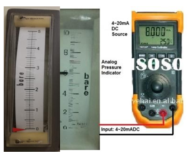
6
Set up test equipment for AI as per the diagram shown: Note:1- Separate power supply is not required for Analog Indicator. 2- Only 24VDC for input: 4~20mADC
Pic. 1
7
In case of Analog Indicator, connect the mA source to the AI as per core identification and switch ON the mA source, check the needle of indicator be raise from bottom and reaches to Zero point. Note: View reading of analog indicator perpendicularly on the scale.
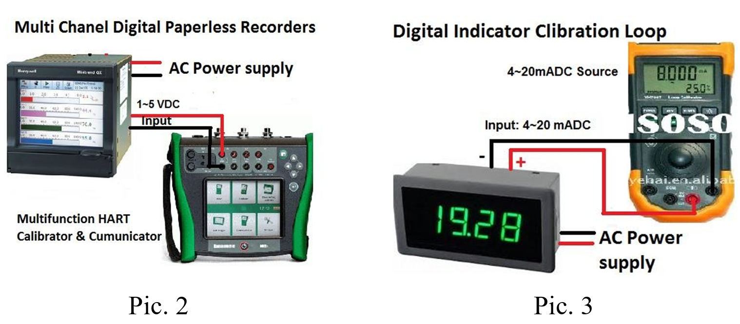
8
Set up test equipment for DI & DR as per the diagrams shown Note:1- Mostly all recorders works with 1~5 VDC Input signal. 2- Digital type of Indicators & recorders having universal inputs. 3– This set up can be used with separate AC power supply. 4- Digital indicator and recorder are only required for configuration. These are so accurate that calibration is not required. Even that we can check the output values by injecting inputs.
9
If DI / DR are removed from the panel, then connect the separate power supply wires to power terminals and then switch it ON the power.
10
Connect the Digital Precession Multifunction HART Calibrator to the Digital indicator or recorder, requiring channel input terminal with core identification and Switch it ON. Now select the type of output. (1~5VDC / 4~20mADC).
Note: 1- If input signal: 4~20mADC then signal in % is: (4mA=0%, 8.0mA=25%, 12mA=50%, 16ma=75% & 20mA=100%) 2- If input signal: 1~5VDC then signal in % is: (1V=0%, 2V=25%, 3V=50%, 4V=75% & 5V=100%)
11
If it is required to confirm and check the configuration of DI / DR. then open set up option:
Check the channel No. Check the input type. (1~5VDC / 4~20mADC)) Check the Service name (like: Pressure, level, Flow etc.) Check the range. (-10000 ~0~10000) Check the engineering unit. (mm WC, Bar, Meter, M3/Hr.)
Note: If any configuration is required to change. Ask engineer for further process.
Calibration
12
Apply 0 % signal to the AI / DI / DR from the mA / V source. View the reading on the indicator / recorder. It should show (0.00) value. Note: (1) Mostly all Mfg. Companies manufacturing analog indicators with Zero and Span adjustment screws as shown in Pic. 1. (Yamatake Co. provides Zero and Span adjustment screws) installed in Distillation Plants. (2) Some Mfg. companies only provide Zero adjustment screw. Span screws are not provided. In these indicators we can adjust only zero. (YEW & Bailey Co. only provided Zero adjustment screw) Installed in Boiler 1~4 and Turbine 1~4. (3) In case of only zero adjustment screw, If there is error more than designed acceptable error, then divide this error by adjusting zero adjustment screw on all values (0, 25%, 50%, 75% and 100%). If still error is more than designed error, then replace the indicator with new indicator.
13
Apply 100 % signal and view the reading, it should show 100% value. Note: The input can be applied in increasing and decreasing order (ascending and descending order) i.e.: 0%, 25%, 50%, 75% & 100% and vice versa.
14
If above both values are correct then apply middle 3 points input signal (25%, 50% & 75%) on the calibrator and see the reading on the indicator / recorder. It should show all values according to the input signal.
15
Check these input / output values in sending / descending orders.
16
If all 5 reading are matched with all 5 input signals then record these values in as found column or before calibration column. If error is within limit and acceptable then go to step 23.
17
If error is more than the designed error then instrument needs to be calibrated
18
Apply 0% signal to the AI from the mA / V source. View the reading on the indicator / recorder. Adjust the zero from zero adjustment mechanical screw. In case of DI & DR, there should be Potentio meter on the PCB. (If available).
19
Apply 100% signal from mA / V source Adjust the span from span adjustment mechanical screw. In case of DI & DR, there should be Potentio meter on the PCB. (If available).
20
Repeat step 18 & 19 till the 0% and 100% reading should match with input signal.
21
Again apply 5 points (0%, 25%, 50%, 75% and 100%) signal on the mA / V calibrator in ascending and descending order and view the readings on the indicator / recorder. It should match according to the input signals and error should be in limit.
22
If calibration adjustment is successful, record the after adjustment results on the calibration sheet in after adjustment column.
23
The analog indicator / digital indicator / digital recorder calibration should be inspected by Inspector and Quality Inspector for witness and record these values to sign the certificate after completion of job.
Completion
24
Once the test is completed, remove the test equipment and clean the tested device.
25
Reconnect all wires at original positions according to the core identification. (If it was removed then install the analog indicator / digital indicator / digital recorder back to its position).
26
Switch ON the power supply and commission the analog indicator / digital indicator / digital recorder. Check the reading. It should be 0% if unit is shut-down or under annual maintenance. If process is temperature then it should show ambient temperature.
27
Complete the check and calibration sheet and handover to the concerned I&C Engineer for inspection and signature.

 Note: 1- Mostly all recorders works with 1~5 VDC Input signal. 2- Digital type of Indicators & recorders having universal inputs. 3– This set up can be used with separate AC power supply. 4- Digital indicator and recorder are only required for configuration. These are so accurate that calibration is not required. Even that we can check the output values by injecting inputs.