1- Temperature Gauge (Direct Mount on the pipe)
2- Temperature Gauge (Remote Mount with long capillary)
| Procedure | General Procedure for all Power Stations. | ||
| Title of Job | Maintenance Check & Calibration | ||
| Manpower | Instrument Technician Using PPE (Personal Protective Equipment) | ||
| Safety Document | Maintenance Work Permits. & SCC (Safety Clearance Certificate) If Required | ||
| Tools/ Special | I &C Tool Kit + any special tools (if Required) | Test Equipment | |
| Tools | |||
| Test Equipment: | Note: Select test equipment according to the max. Range of Temperature gauge. 1– Ice pot ( For “0” degree C) 2- Boiling water (For 100 degree C) 3- Low Temperature Bath (Dry block) (From Ambient to 200 Degree C) 4- High Temperature bathe (Dry block) (From Ambient to 600 Degree C) 5- Digital precession temperature Calibrator. |  Digital Temp. Bath & Calibrator Digital Temp. Bath & Calibrator | |
| Stores & Materials | Cleaning spray, brush and cloth | ||
| Job Description | ||
| Process | Steps | During Maintenance |
| Isolation & Removal | 1 | Direct mount temperature gauge: Remove the direct mount Temperature gauge from thermowell carefully by opening upper nut of thermo well. Note: Thermo well should not be removed from the pipe unless there is a problem.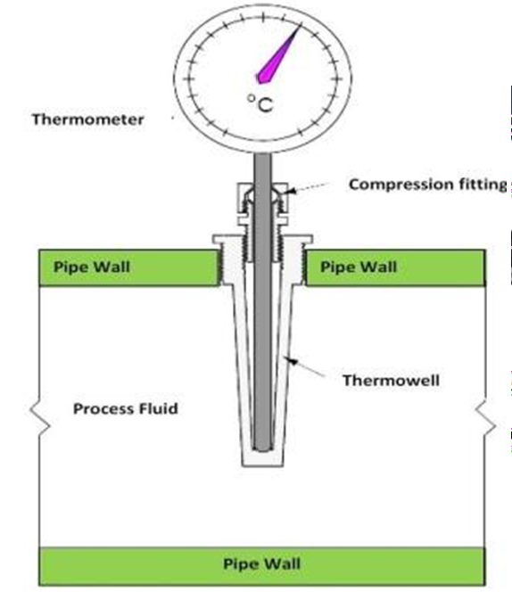 |
| 2 | Capillary type temperature gauge: Remove the temperature sensor (bulb) form the thermo well. Note: If required to remove the temperature gauge completely from the panel with capillary then remove the capillary from the tray carefully. Open the mounting screws / bracket of gauge from the panel and take out gauge from the panel. | |
| 3 | Inspect the Temperature Gauge for external physical damage, general appearance & fitness. (Check whether cover seals are intact). | |
| 4 | Carry out the Temperature Gauge external cleaning, using a brush and approved Cleaning spray to remove contamination or solid particles. | |
| Preparation | 5 | Write all the details of temperature gauge: tag no., range, service and unit no. in the calibration sheet. |
| 6 | Before starting the calibration, compare ambient temperature on the digital temperature calibrator and the gauge to be calibrated. Ambient temperature should same on both. If it does not match then go to next step. | |
| 7 | Set up the test equipment as shown in the diagram: 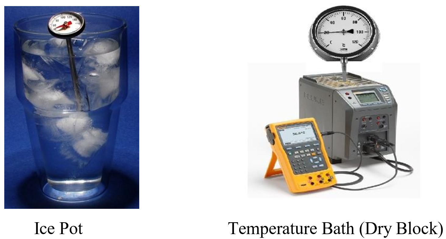 | |
| Calibration | 8 | To check the “0”degree of the gauge. We need to put sensor (bulb) in ice box or ice filled glass. Wait till needle of gauge reaches to “0” degree and stop moving. If it is not on “0” remove the cover and adjust the needle on (0) or remove the needle by puller and fix on “0” |
| 9 | After checking (0) degree, remove the bulb from ice pot and Insert the bulb in the well of temperature bath. Switch on the bath and set the temperature according to the gauge scale. | |
| 10 | Apply the correct temperature setting to the Temperature dry bath, corresponding to required % of the process. Change the process from 25% to 100%, (4 points calibration) Note: 1- At every point, wait for the gauge needle to stop moving and reaches to its correct temperature. 2- Remote type temperature gauge (Gauge with long capillary) requires long time to stabilize the reading on each point. It will take long time to calibrate the gauge. 3- We can use normal water to cool down the bulb for quick check of each point. 4– The input temperature can be applied in increasing and decreasing order (ascending and descending order) i.e.: 0%, 25%, 50%, 75% & 100% and vice versa. | |
| 11 | Record these reading on the check and calibration sheet in the as found column or before calibration column. | |
| 12 | If as found results are correct on each point and error is in limit of designed error. Then go to step 22. |
| 13 | If there is difference in reading & error is more than designed error and adjustment is required, remove the front cover, pointer and scale plate to gain access to span adjustment. | |
| 14 | Check the hair spring, gears of rack & pinion, bushings, and the bourdon tube for possible deformation or puncture of spiral. Apply small amount of silicon grease to the moving parts (Repairs or replace internal parts if damaged). | |
| 15 | Install scale & pointer after making internal inspections. | |
| 16 | Insert the bulb in ice box and wait to stabilize the temperature at zero. Adjust the pointer on zero after stabilized. | |
| 17 | Increase and set the maximum temperature on the temperature bath as shown on the temperature gauge and wait till needle stabilizes and stop on the max. Scale of the gauge. | |
| 18 | Observe the difference between standard values (degree C) on the dry bath and temperature gauge to be calibrated. If there is difference more than the error then remove the pointer and scale and adjust the span screw given in between bourdon and span link with sector gear. | |
| 19 | Repeat steps 16, 17 & 18 till 0% & 100%. Values of temperature gauge should be Mach with standard values on the temperature bath or temperature calibrator. | |
| 20 | Now check the repeatability of temperature in percentage (0%, 25%, 50%, 75%, & 100%) by increasing and decreasing the temperature using ice pot and temperature bath. | |
| 21 | If all values are correct and error is in limit then record these values in calibration sheet in after calibration columns. (Error should not be more than the design values). | |
| 22 | The temperature gauge input / output values should be inspected by Inspector and Quality Inspector for witness and record these values to sign the certificate after completion of job. | |
| Completion | 23 | Once the test is completed, remove the test equipment, fix the cover of the gauge properly, and clean the tested device. |
| 24 | Install the temperature gauge back to its position and ensure that Connection are not cross fitted with thermo well that can damage threading. | |
| 25 | Check the condition of the fittings, brackets, vibration suppressers etc. Repair or replace as found necessary. | |
| 26 | Commission the Temperature gauge and check the readings. It should be nearly ambient temperature, because unit is under annual maintenance. | |
| 27 | Check for leakage of thermo well during commissioning. | |
| 28 | Complete the check and calibration sheet and handover to the concerned I&C Engineer for inspection and signature. |