1- Temperature Switch (Indicating type) Called TGA
2- Temperature Switch (Non Indicating type)
| Procedure | General Procedure for all stations. | ||
| Title of Job | Maintenance Check & Calibration | ||
| Manpower | Instrument Technician Using PPE (Personal Protective Equipment) | ||
| Safety Document | Maintenance Work Permits & SCC (Safety Clearance Certificate) If Required | ||
| Tools/ Special Tools | I &C Tool Kit + any special tools (if Required) | Test Equipment | |
| Test Equipment: | Note: Select test equipment according to the max. Range of Temperature Switch. 1– Ice pot ( For “0” degree C) 2- Boiling water (For 100 degree C) 3- Low Temperature Bath (Dry block) (From Ambient to 200 Degree C) 4- High Temperature bathe (Dry block) (From Ambient to 600 Degree C) 5- Digital precession temperature Calibrator. 6– Multi-meter (Ohm Meter) | 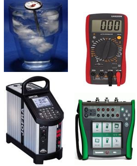 Digital Temp. Bath & Calibrator Digital Temp. Bath & Calibrator | |
| Stores & Materials | Cleaning spray, brush and cloth | ||
Temperature Switch Calibration Procedure
| Job Description | ||
| Process | Steps | During Maintenance |
| Isolation & Removal | 1 | Open the cover of temperature switch and confirm that power supply is OFF by multi meter. Remove wires with core identification from the switch terminal and insulate all wires by insulation tape (Ensure it isn’t in contact with each other, short circuiting or producing any earth). |
| 2 | Direct mount temperature switch: Remove the direct mount Temperature switch from thermo well carefully by opening upper nut of thermo well. Note: Thermo well should not be removed from the pipe. Until there is leak or damaged threads.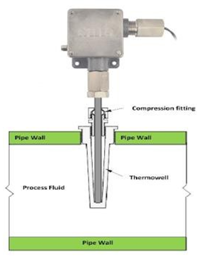 | |
| 3 | Capillary type temperature switch: Remove the temperature sensor (bulb) form the thermo well, remove the capillary form the tray carefully, open the mounting screws / fittings, brackets, vibration suppressers of gauge from the panel and take out gauge from the panel. | |
| 4 | Inspect the Temperature switch for external physical damage, general appearance & fitness. (Check whether cover seals are intact). | |
| 5 | Carry out the temperature switch external cleaning, using a brush and approved Cleaning spray to remove contamination or solid particles. | |
| Preparation | 6 | Write all the details of temperature switch: tag no., range, service and unit no. in the calibration sheet. |
| 7 | Before start the calibration remove the cover of temperature switch and check the contacts of micro switch by ohm meter. Zero resistance should be in micro switch contacts. If resistance is high, clean the contacts by dry contact cleaning spray. If not possible then change the micro switch with new one. | |
| 8 | Set up the test equipment as shown in the diagram: Test loop of temperature switch. Temperature Bath (Dry Block) 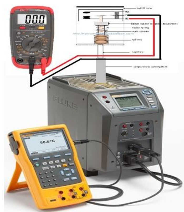 | |
| Calibration | 9 | In case of indicating type temperature switch (TGA). Read Standard calibration procedure to calibrate temperature gauge. After calibrating gauge go to next step for calibrating switch. |
| 10 | Note down the SP values (1SPDT or 2SPDT) on the calibration sheet supplied by MEW for set and reset (increasing SP for high temperature switch & decreasing SP for low temperature switch) and contacts (NO or NC) used in it. | |
| 11 | Apply the correct temperature setting to the Temperature dry bath, corresponding to required SP to the temperature switch (1SPDT or 2SPDT). Either increasing or decreasing corresponding to the use of switch for high or low alarms. |
| Note: 1- Every time slowly increase or decrease temperature till it changes the position of switch from NO to NC or NC to NO, in high or in low alarm for set and rest 2- Remote type temperature switch (switch with long capillary) required long time to stabilized temperature on each set & reset. Don’t be hurry. It will take long time to calibrate the temperature switch. | ||
| 12 | Repeat step 11 to confirm the set and reset values for each switch. | |
| 13 | Record the input temperature set & resets values (SP) in the Check and Calibration Sheet in the as found or before calibration column. | |
| 14 | If set and reset values (SP) are correct and matching with MEW supplied SP then go to step 24. | |
| 15 | If set and reset values differs from the MEW supplied SP. Then SP adjustment is required and goes to next step. | |
| 16 | Remove main cover or any additional covers necessary to gain access to the set and differential adjustments screws. | |
| 17 | Inspect the temperature Switch for Internal physical damage, general appearance and fitness. Check the internal moving parts are free to move. Check that the cover seals are in good condition. Record findings on the check and calibration sheet. | |
| 18 | Carry out temperature switch internal cleaning, if necessary, using a brush, cleaning spray and dry air. The micro switch contacts are to be cleaned by appropriate contact spray. (If possible) | |
| 19 | Increase the temperature and check the set value when micro switch changes his position from NO to NC or NC to NO on the contact tester or Ohm meter and adjust the set value screw till it reaches to the set point. | |
| 20 | Decrease the temperature and check the reset value on the contact tester or Ohm meter (Micro switch will change from NC to NO or NO to NC) Adjust the differential adjustment screw (if available) to get exact value of rest. | |
| 21 | Repeat steps 19 & 20 for (1SPDT & 2SPDT) by increasing and decreasing temperature. Adjust the SP screw as set and rest values (SP) until it reaches at correct values and match with MEW SP. | |
| 22 | If the temperature switch adjustments are over, check & confirm by the repeatability of the switch for the design setting of SP. | |
| 23 | If the calibration adjustment is successful, Record the after adjustment results (Re-adjusted SP values) on the check and calibration sheet in after adjustment column. | |
| 24 | The temperature switch SP (Set & Reset values) should be inspected by MEW Inspector and Quality Inspector for witness and record these values to sign the certificate after completion of job. |
| Completion | 25 | Once the test is completed, remove the test equipment, fix the cover of the temperature switch properly and clean the tested device. |
| 26 | Install the temperature switch back to its position and ensure that connection are not cross fitted with thermo well that can damage threading. | |
| 27 | Check the condition of the fittings, brackets, vibration suppressers etc. Repair or replace as found necessary. | |
| 28 | Connect the removed wires on it correct terminals. Commission the Temperature switch. Check the alarm position in control room is Matching with its logic. | |
| 29 | Check for leakage of thermo well during commissioning. | |
| 30 | Complete the check and calibration sheet and handover to the concerned MEW I&C Engineer for inspection and signature. |