1- Temperature Transmitter (T/C to E.I Converter)
2- Temperature Transmitter (RTD to E.I Converter)
| Procedure | General Procedure for all stations. | ||||
| Title of Job | Annual Maintenance Check & Calibration | ||||
| Manpower | Instrument Technician Using PPE (Personal Protective Equipment) | ||||
| Safety Document | Maintenance Work Permits & SCC (Safety Clearance Certificate) If Required | ||||
| Tools/ Special | I &C Tool Kit + any special tools (if Required) | Test Equipment | |||
| Tools | |||||
| Test Equipment: | Note: Select test equipment according to the max. Range of Temperature Transmitter. 1– Ice Pot 2- Boiling Water 3– mV generator with Temp. Compensator. 4- Thermocouple temperature calibrator. 5- RTD temperature calibrator. 6- Multifunction temperature calibrator. 7- Digital precession temperature Calibrator. 8– Digital HART Calibrator & Communicator. | 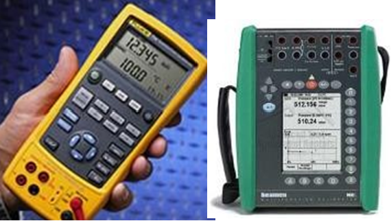 Digital Multifunction Calibrator Digital HART. Calibrator | |||
| Stores & Materials | Cleaning spray, brush and cloth | ||||
| Job Description | ||
| Process | Steps | During Maintenance |
| Isolation & Removal | 1 | There are two types of Temperature Transmitters. Direct mount type TT. Mounted in field. 1) Thermocouple type TT. 2) RTD type TT. 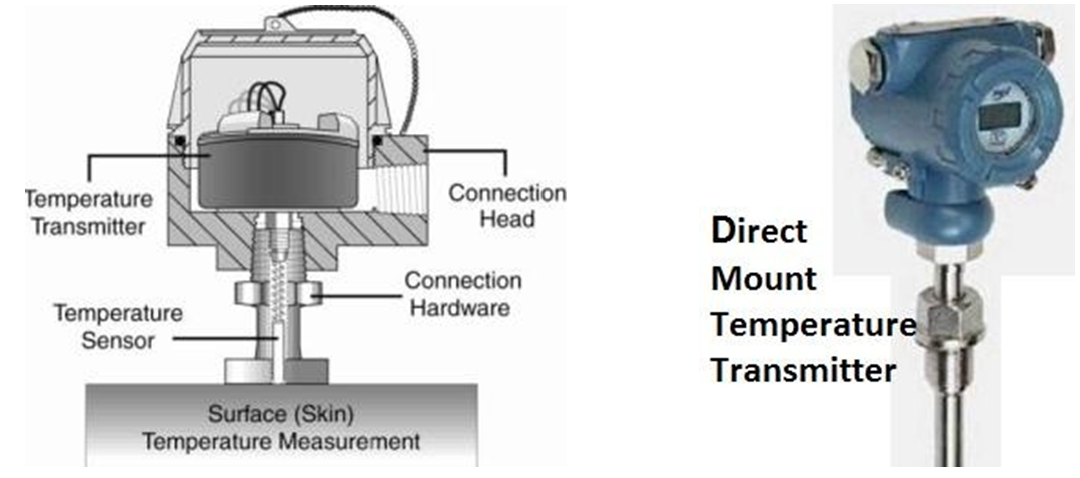 |
| 2 | Remote mount type TT. Mounted in remote area or in control room. 1) Thermocouple type TT. 2) RTD type TT. 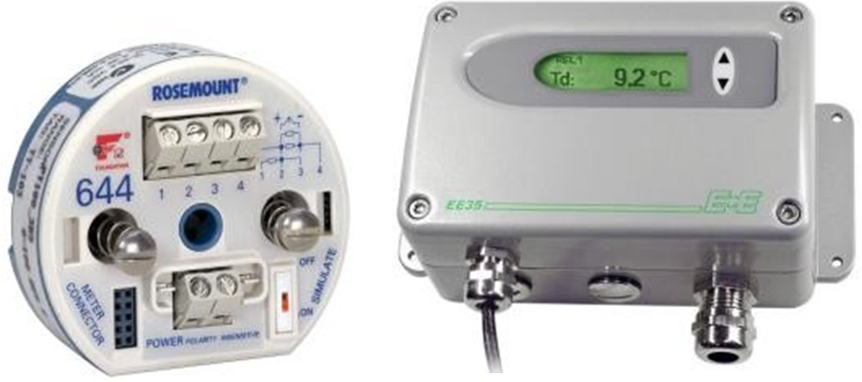 | |
| 3 | Open the cover of temperature transmitter and remove the wires of T/C or RTD with core identification from the transmitter terminals. | |
| 4 | Check the power supply by multi mete and it should be OFF. Remove the wires and insulate all wires by insulation tape (Ensure it isn’t in contact | |
| with each other, short circuiting or producing any earth). Remove the fittings, brackets, vibration suppressers etc. (If available). | |||
| 5 | 1) Direct mount Temperature transmitter: Remove the temperature transmitter from the well by opening upper nut, which is tightened in the well. | ||
| 6 | 2) Remoter mount type Temperature Transmitter: Remove from the field panel or control room panel for calibration. (There are many types of TT as shown above pictures. These can also be module type) Note: These transmitters can be calibrating at their own locations. | ||
| 7 | Inspect the Temperature transmitter for external physical damage, general appearance & fitness. (Check whether cover seals are intact). | ||
| 8 | Carry out the temperature transmitter external cleaning, using a brush and approved Cleaning spray to remove contamination or solid particles. | ||
| Preparation | 9 | Write the all details of Temperature Transmitter, Temperature range in degree C, input T/C (Type) or RTD (Type), Tag No., Service and Unit No. in the Calibration sheet. | |
| 10 | Open the cover of the Transmitter and set up the test equipment as per the diagram shown. 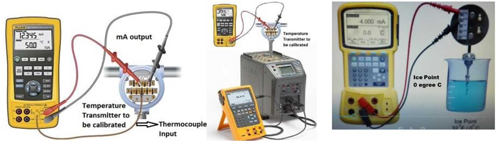 M M.F. Temperature Dry bath tester Cold & Hot water tester Calibrator Remote Mount TT OR Direct mount TT | ||
| 11 | Select the connections according to the measuring principle (T/C or RTD) for multifunction temperature calibration.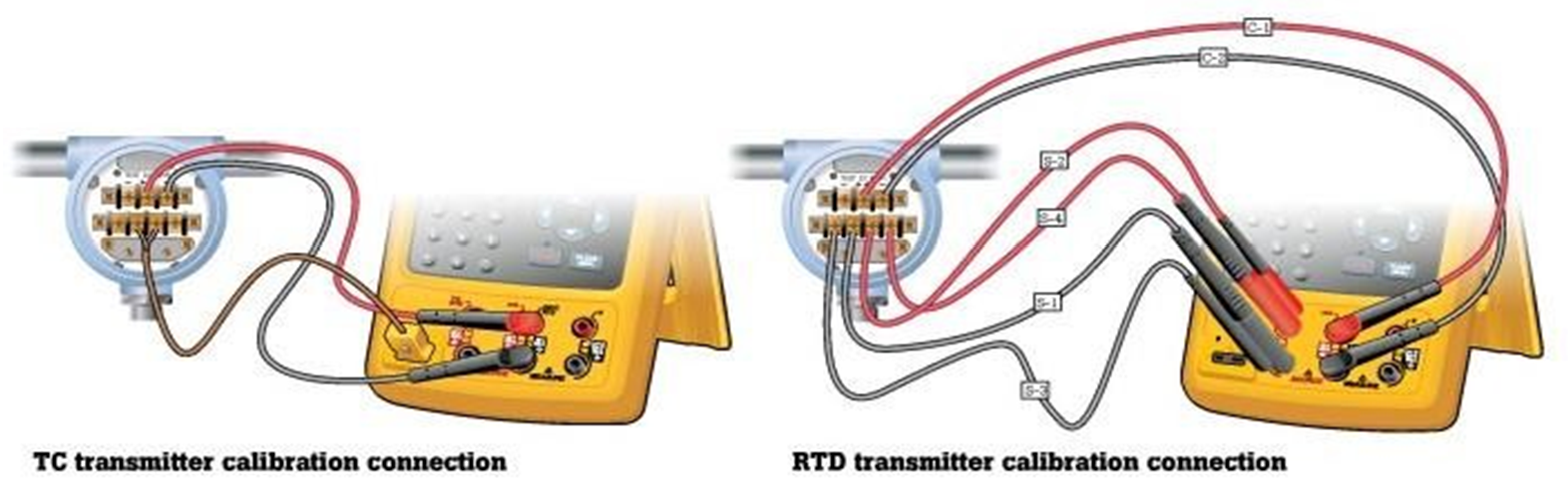 | ||
| 12 | Switch ON the power supply to the temperature transmitter. Now switch on the multi-function temperature calibrator and select the option input type. If it is thermocouple temperature transmitter then select T/C on the multifunction temperature calibrator, then select type of T/C (“T”, “J”, “K” type or any other type) used in the system. Note: Multifunction temperature calibrator will automatically compensate the ambient temperature according to the type to T/C. | ||
| 13 | If it is RTD temperature transmitter select RTD on the multifunction temperature calibrator and then select type of RTD (“PT100 ohms”, type or any other type) used in the system. |
| 14 | Select temperature transmitter range in degree C, (0-100C, or 0-300C) on the multifunction temperature calibrator which will be shown on the indicator in control room. (Collect the temperature range from MEW I & C Engineer). | |
| 15 | Select the output 4 – 20mADC on the multifunction temperature calibrator. | |
| Calibration | 16 | We have two methods of temperature transmitter calibration. 1- Calibration by multifunction temperature calibrator (this is called cold calibration procedure) 2- Calibration by temperature bath or by water. (Cold water and hot water calibration) (This is called hot calibration procedure) |
| 17 | 1st method of TT calibration. (Cold Calibration Procedure) Calibration by multifunction temperature calibrator. Apply 0% input temperature “0”degree C from the multifunction temperature calibrator and see the output of Transmitter, it should be 4.00mADC. | |
| 18 | Apply 100% input temperature (full range temperature) in degree C from the multifunction temperature calibrator and see the output of Transmitter, should be 20.00mADC. Note: The temperature can be applied in increasing and decreasing order (ascending and descending order) i.e.: 0%, 25%, 50%, 75% & 100% and vice versa. | |
| 19 | Now apply input temperatures 25%, 50% 75% from the multifunction temperature calibrator and see the outputs of Temperature Transmitter (TT), it should be according to the percentage of input temperature. 8mADC, 12mADC, & 16mADC. | |
| 20 | 2nd method of TT calibration. (Hot Calibration Procedure) Calibration by temperature dry bath or by cold water and hot water test. Set up the test equipment as shown below: | |
| 21 | Insert the temperature transmitter sensor (Bulb) in ice water for “0” degree C as shown in diagram. Wait for stabilization of temperature and see the output of Transmitter reaching 4.00mADC.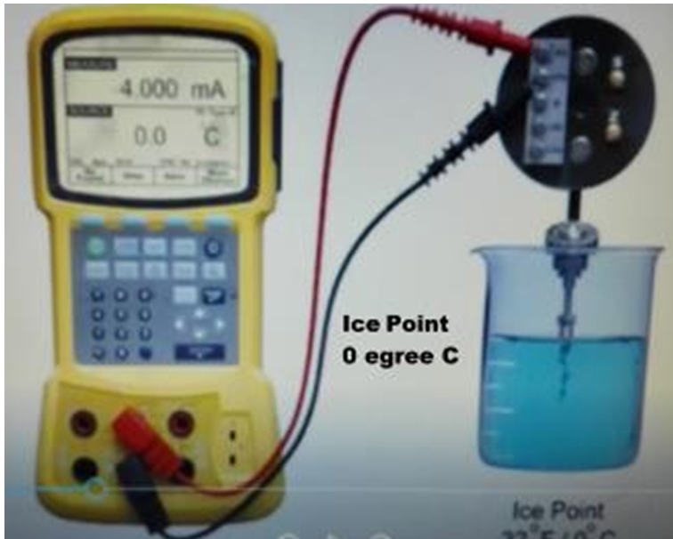 | |
| 22 | Now heat up the water by burner till it starts boiling (100 degree C) i.e. 100% temperature as shown in diagram. Now wait for temperature to stabilize and see the output of Transmitter, it should reach to 20.00mADC.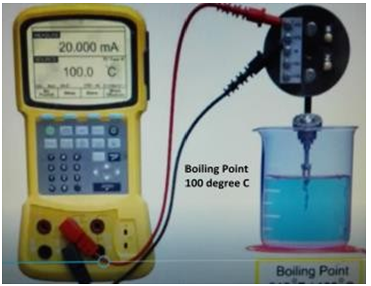 |
| 23 | In the above both procedures if temperature is correct and matching with input temperature at 0%, 25%, 50% 75% & 100% then record the results on the check and calibration sheet in the as found column or before calibration column | |
| 24 | If as found results are correct and error on all points are in limit of designed error. Then go to step 32. | |
| 25 | In case of difference in reading, error is more than designed error then adjustment is required go to next step. | |
| 26 | Apply 0% input temperature “0” degree C from the multifunction temperature calibrator or dip the sensor bulb in ice water & wait for stabilizing the output of Transmitter. Now adjust the zero adjustment screw to bring output current exactly at 4.00mADC. | |
| 27 | Apply 100% temperature to the transmitter from the multifunction temperature calibrator or dip the sensor bulb in boiling water wait for stabilizing the output of Transmitter. Now adjust the span adjustment screw to bring current output exactly at 20.00mADC. | |
| 28 | Repeat steps 26 and 27 till 0% & 100%. Values of temperature & output of transmitter (4-20mADC) should match according to the % tag of input temperature. | |
| 29 | If with 0% input temperature matches with output of TT is 4.00mADC and 100% input temperature matches with output of TT is 20.00mADC. Then check the other 3 middle points (25% input temperature = 8mADC, 50% input temperature = 12mADC and 75% input temperature =16mADC.) | |
| 30 | Check repeatability by increasing and decreasing temperature input and confirm all 5 points (0%, 25%, 50%, 75%, & 100%) output values match with standard values 4-20mADCand within acceptable error. | |
| 31 | Record input and output values according to the percentage in calibration sheet in after calibration columns. | |
| 32 | The temperature transmitter calibration should be inspected by MEW Inspector and Quality Inspector for witness and record these values to sign the certificate after completion of job. | |
| Completion | 33 | Once the TT calibration is completed, remove the test equipment. Install the Temperature transmitter back to its position. |
| 34 | Reconnect the power supply and Thermocouple or RTD wires on its original terminal according to the core identification. Fix the cover properly and clean the tested device. | |
| 35 | In case of direct mount TT, ensure that connection are not cross fitted with thermo well that can damage threading. | |
| 36 | Check the condition of the fittings, brackets, vibration suppressers etc. Repair or replace as found necessary | |
| 37 | Commission the Temperature Transmitter and check the readings. It should be nearly ambient temperature, if unit is under annual maintenance. | |
| 38 | Complete the check and calibration sheet and handover to the concerned MEW I&C Engineer for inspection and signature. |