1- Thermocouple Test (“T”, “J”, “K” or any other type)
Procedure
General Procedure for all stations.
Title of Job
Annual Maintenance Check & Calibration
Manpower
Instrument Technician Using PPE (Personal Protective Equipment)
Safety Document
Maintenance Work Permits. & SCC (Safety Clearance Certificate) If Required
Tools / SpecialTools
I &C Tool Kit + any special tools (if Required)
Test Equipment
Test Equipment:
Note: Select test equipment according to the max. Range of Thermocouple.1– Ice pot ( For “0” degree C) 2- Boiling water (For 100 degree C) 3- Low Temperature Bath (Dry block) (From Ambient to 200 Degree C) 4- High Temperature bathe (Dry block) (From Ambient to 600 Degree C) 5- Digital precession temperature Calibrator. 6– Multi function multi-meter (AVO Meter)
Digital Temp. Bath & Calibrator
Stores & Materials
Cleaning spray, brush and cloth
Job Description
Process
Steps
During Maintenance
Isolation
1
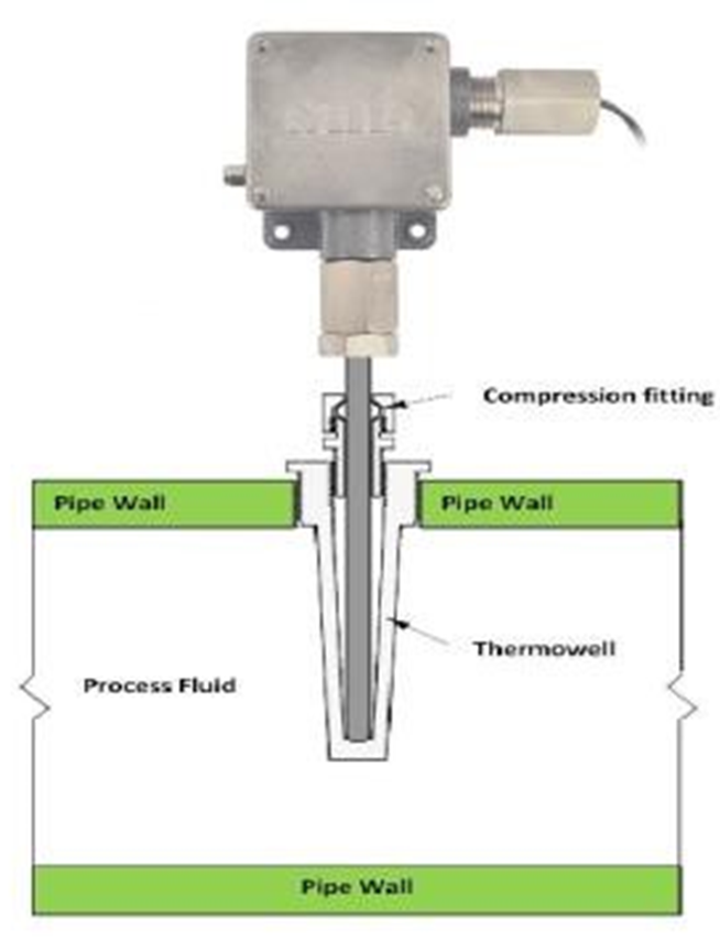
Open the cover of thermocouple. Remove the wires by the core identification and insulate all wires by insulation tape (Ensure it isn’t in contact with each other, short circuiting or producing any earth). Remove the fittings, brackets, vibration suppressers etc. (If available).
&
Removal
2
Remove thermocouple from thermo well carefully by opening upper nut of thermowell.
Note: Thermo well should not be removed from the pipe until there is a problem.
3
Thermo well should be removed if there is leak or need cleaning due to scaling, dirt deposits and sediments. After cleaning well and scaling is removed, fix back with rapping new Teflon tap properly. Carefully tight so much that there should be no leak from threads of thermo well.
4
Carry out the thermocouple external cleaning, using a brush and approved cleaning spray to remove contamination or solid particles.
5
Inspect the thermocouple for external physical damage, general appearance & fitness. (Check whether cover seals are intact).
Preparation
6
Write the all detail of thermocouple, Tag No., Temperature range showing on the indicator in control room, Type of thermocouple (T, J, and K), Service and Unit No. in the Test sheet.
7
Test of Ohms meter: To check continuity, selects the knob of multi meter on ohms or symbol of ohms (Ω). To confirm that multi meter is working in good condition. Touch both wires with each other. If it shows “0” ohm. When opening wires shows (OL) or infinity. This means multi meter is healthy and can be used.
8
Continuity test of thermocouple: Check the continuity of thermocouple by ohm meter by connecting both wires with both terminals of thermocouple. If It shows “0” ohms or near to zero ohms. This shows that thermo couple is healthy
9
Unground test of thermocouple: If thermocouple is un-grounded then connects one wire of ohm meter with body of thermocouple and other with one terminal. It should show infinity resistance or OL (over limit). Same should do with 2nd terminal.
10
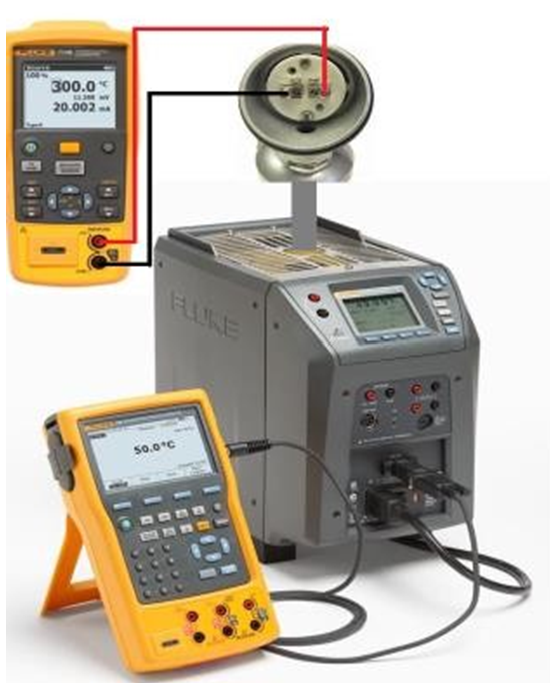
Set up test equipment as per the Diagram shown in picture. Remove cover of thermocouple as required to connect up the test equipment to Terminals. Confirm the polarity of test equipment is connected with right polarity of thermocouple.
TestProcedure
11
There are two methods of test.
1) 1st Method (T/C Output mV test by Multi meter).
2) 2nd Method (Temperature test by Digital
precession
temperature Calibrator)
12
1st Method (mV test by Multi meter) Select the knob of multi-meter on the “mVDC” and connect both wires to both terminals according to the polarity.
13
Insert thermocouple bulb in the ice pot. Give some time to stabilize till stop changing mVDC output of thermocouple on multi meter.
14
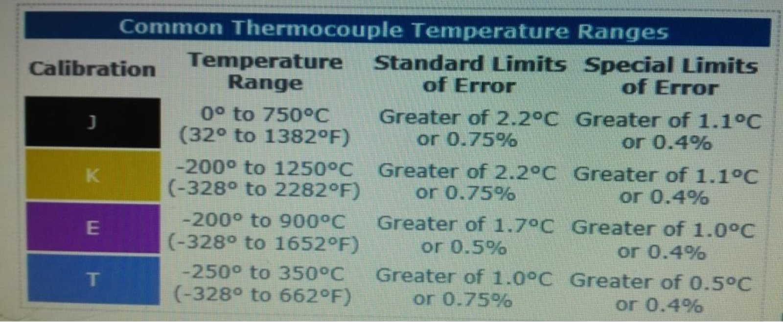
Note down “mVDC” and compare with standard chart matches with the type of T/C (T, J, and K Type). It should match with “0” degree C.
15
Now switch on the temperature bath and set a temperature setting on it (according to the thermocouple type) and start heating the thermocouple bulb. Note: Set temperature should not be more than thermocouple type or temperature shown on the indicator in control room). If set value is less than the max. Value is better and safe.
16
Max ranges of diff. type of thermocouples.
17
Watch on the multi meter. It starts to increase “mVDC”. Let stabilize the temperature which is set on the temperature bath & Note down the setter value.
18
Now we can match this “mVDC” value with the standard temperature chart value and confirm that how much temperature will be acting on the thermocouple sensor bulb.
19
If “mVDC” is matching with the temperature shown in the standard chart related to the thermocouple type, means thermocouple is in good condition.
20
2nd Method (Temperature test by multi-function Digital precessiontemperature calibrator. Connect Digital precession temperature calibrator with thermocouple, which can show direct temperature on the meter and connect both wires to both terminals according to the polarity.
21
Switch on the calibrator and select T/C on the calibrator and then select the type of thermocouple, like “J type” “T type” or “K type”.
22
Insert thermocouple sensor (Bulb) in ice pot and wait to stabilize temperature at 0 C.
23
Watch on the temperature calibrator. It starts to decrease temperature. Let stabilize up to “0” degree. If it shows “0” degree. Means thermocouple is healthy.
24
Now insert the thermocouple sensor in the temperature dry bath and switch ON the bath. Set 100 C or 200 C temperature on the bath.
25
Watch on the Digital precession temperature calibrator. It starts to increase temperature. Let stabilize the temperature on the calibrator & compare with the set temperature on the bath. Both temperatures should be same. Means thermocouple is healthy and can be used.
26
Note down the set temperature and shown temperature on the temperature calibrator in the test sheet.
27
The thermocouple test procedure should be inspected by MEW Inspector and Quality Inspector for witness and record these values to sign the certificate after completion of job.
Completion
28
Once the test is completed, remove the test equipment and clean the tested device.
29
Fix back T/C to its position and ensure that connection are not cross fitted with thermo well that can damage threading.
30
Reconnect the Thermocouple wires on its original terminal according to the core identification. Fix the cover properly and clean the tested device.
31
Check the condition of the fittings, brackets, vibration suppressers etc. Repair or replace as found necessary
32
Check for leakage of thermocouple from the thermo well during commissioning.
35
Complete the check and test sheet and handover to the concerned MEW I&C Engineer for inspection and signature.
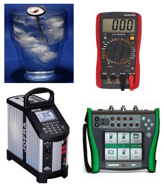 Digital Temp. Bath & Calibrator