- Introduction
- References
- Definitions
- General
- Switchgear and Controlgear Condition Assessment Overview
- Level 1 Inspections, Tests, and Measurements
- Level 2 Inspections, Tests, and Measurements
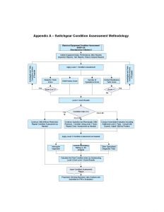
Appendix A – Switchgear Condition Assessment Methodology
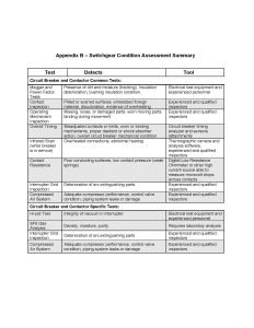
Appendix B – Switchgear Condition Assessment Summary
Appendix C –Condition Assessment Survey Form
Appendix D – Switchgear and Controlgear Condition-Based Alternatives
Appendix E – Switchgear and Controlgear Inspection Checklist
1. Switchgear and Controlgear Introduction
Major investment in replacing aging electrical equipment is required to assure the continued viability and cost-effectiveness of existing Company’s assets. Successful strategic planning for capital investments in existing facilities requires consideration and balancing of many factors.
Any corporate and big company knows the importance of objectively assessing the condition of existing equipment to make informed and sound business decisions for identifying and prioritizing investments in their replacement or life extension. FPD, CSD and POD joined together to create a framework to streamline and improve the evaluation of the condition of electrical switchgear and controlgear to support asset management and risk-based resource allocation.
These guidelines provide a method for determining a Condition Index (CI) from the results of specified equipment inspections, testing, and measurements which will be utilized to objectively score Criterion 8 “rate the equipment condition” of SAEP-136 Electrical Equipment Management of Obsolescence.
1.1 Purpose
The purpose of this article is to provide guidance on the condition assessment of electrical switchgear and controlgear to support the planning process for managing aging electrical equipment in Saudi Aramco facilities.
1.2 Scope
This provides guidelines for making Condition Based Assessments on electrical switchgear and controlgear currently in questionable operational condition. The methodology applies to air-insulated metal-clad and metal-enclosed switchgear and controlgear, as well as to free-standing outdoor type circuit breakers. The circuit breakers and contactors in the switchgear can be air magnetic, air blast, SF6 gas, and vacuum.
2. Switchgear and Controlgear References
Hydro Plant Risk – Appendix E2-Circuit breaker Condition Assessment
Assessment Guide – US Army Corp of Engineers, (Sept. 2006)
3. Switchgear and Controlgea Definitions
Condition: The existing state of the component or equipment with respect to function and fitness.
Condition Assessment: The process of objectively evaluating the condition of a piece of equipment or a system using a uniform process and guidelines.
Condition Indicators: Individual components of an overall condition assessment. Typically, standardized inspections and tests that are evaluated in a common manner.
Condition Index: The outcome of a condition assessment. An overall numerical rating between 0 and 10 which describes condition, with higher numbers equating to better condition.
Equipment Condition: Suitability of the equipment for continued operation in the intended environment as determined by evaluation of the results of inspections and tests.
Exercise: To operate equipment in such a manner that it performs all its intended functions to allow observation, testing, measurement, and diagnosis of its operational condition.
Inspection: Examination or measurement to verify whether an item or activity conforms to specified requirements.
Mechanical inspection: Observation of the mechanical operation of equipment not requiring electrical stimulation, such as manual operation of circuit breaker trip and close functions. It may also include tightening of hardware, cleaning, and lubricating.
Verify: To investigate by observation or by test to determine that a particular condition exists.
Visual inspection: Qualitative observation of physical characteristics, including cleanliness, physical integrity, evidence of overheating, lubrication, etc.
Partial discharge test: A test undertaken with a suitable instrument, to determine the presence or otherwise of partial discharges within electrical insulation components or across the surface of electrical insulation components, which is of a magnitude likely to result in material degradation of the insulating properties of the component.
Partial Disharge Measurement: An instantaneous measurement of the magnitude of partial discharges within electrical insulation components or across the surface of electrical insulation components.
Partial Discharge Monitoring: Continuous monitoring of the magnitude and location of partial discharges within electrical insulation components or across the surface of electrical insulation components.
4. Switchgear and Controlgea General
4.1 Switchgear and Controlgear Main Components
A switchgear or controlgear assembly consists in the following major components:
Metal enclosure
Busbar and cable compartments
Control, measuring, and protection compartment
Power-switching device compartments (circuit breakers or fused contactors)

Figure 1 – Typical Cross-Section of a Medium-Voltage Switchgear or ControlgearThe metal enclosure serves as safety protection to personnel from energized parts and as environmental protection. Generally, only corrosive agents affect it. If the equipment is located indoors in a controlled environment, the enclosure can last indefinitely without any major maintenance intervention. On the other hand, if the equipment is located outdoors in a humid and corrosive atmosphere, it will require intensive maintenance and may only last 20 years or less.
The busbar and cable compartments interconnect the various switching devices with the external circuit cables. Humidity and corrosion agents have harmful effects on the insulation system. Additionally, heat produced by the electric current is the key factor that deteriorates the conducting parts and connections, not age.
The control and protective devices operate only when they are called upon. Typically, when this happens, they activate for only a few milliseconds. Ambient temperature and corrosive agents may shorten their life. Starting in the 1980’s, control, measuring, monitoring, and protection systems did change
significantly from discrete electromechanical devices to multi-function microprocessor-based systems. These advances are adding functionality, speed, and more information (brain) to the traditional switching equipment.
The power-switching device is the most expensive component and exposed to wear and deterioration during normal operation. This component is also subject to changes in technology. The main functions of a circuit breaker or a motor starter (fused contactor) are to control electric current flow (closing/opening) and to clear out short circuit currents or other abnormal conditions (trip), as commanded by the operator, the control system, or the protection relaying.
The industry has been utilizing oil and air as the interrupting medium for almost eighty years. Hexafluoride (SF6) gas and vacuum technology entered the market thirty five years ago. Oil was discontinued from switchgear use while air continues being utilized as interrupting medium in low voltage equipment. Thirty years ago, vacuum interruption became the predominant technology up to 34.5 kV, while SF6 continues to be the only choice at higher voltages.
4.2 Switching Technologies
There are several switching technologies used in switchgear across Saudi Aramco facilities: air magnetic/air blast, SF6, and vacuum. Air Magnetic breakers and contactors are air insulated, spring operated, and use magnetically contoured arc chutes to elongate and cool the arc. They are often installed in metal clad switchgear and can be removed entirely for maintenance.
The dielectric condition of the breaker and contactor can be measured and trended by performing megger and power factor tests on the fully assembled device, including the arc chutes. The main and arcing contacts should be inspected for signs of wear including pitting, scoring, or overheating and burning. It is normal to show more wear on the arcing contacts than the main contacts.
All components of the operating mechanism should be checked for loose or broken parts, missing retainers or other hardware, excessive wear on moving parts, and for binding during movement. The fully assembled circuit breaker should be tested to determine breaker operation and timing is within original manufacturer tolerances.
Vacuum breakers and contactors utilize a pair of main contacts encapsulated in a sealed vacuum bottle. The actual contact separation is very small as there is no medium that the arc would ionize to sustain itself after the contacts open. The dielectric condition of the breaker or contactor can be measured and trended by performing power factor tests on the fully assembled device.
The current carrying contacts are not accessible. The operating rod for the moving contact is scribed with a mark whose position with the contacts closed can be noted and compared to a reference mark. If the scribe mark and the reference mark are in alignment, the contacts have worn to the point of needing to be replaced. The vacuum level in the bottle can be checked by performing a hi-pot test on the bottle per the manufacturer’s instructions.
Vacuum circuit breakers and contactors have fewer components and lower operating forces than other types. Some of the Level 1 tests are not useful in determining whether the breaker is a candidate for replacement. For these reasons, the only condition indicator used for vacuum breakers is O&M History. This is important for contactors and CB controlling motors.
SF6 breakers utilize sulfur hexafluoride gas to both insulate the current carrying parts and to aid in interrupting the arc. The dielectric condition of the breaker can be measured and trended by performing megger and power factor tests on the fully assembled breaker. The current carrying contacts of an SF6 breaker are not accessible during routine maintenance. Contact engagement may be discernible by measuring the travel of the operating mechanism. The complete circuit breaker should be tested to confirm correct breaker operation and that timing is within original manufacturer tolerances.
5. Switchgear and Controlgear Condition Assessment Overview
The equipment condition assessment and decision-making process involves three distinct phases: Level 1 assessment, Level 2 assessment, and a Business Case Analysis This Best Practice covers Levels 1 and 2 assessments. Business Case Analysis is normally independently conducted by FPD and it is not part of this guidelines.
5.1 Level 1: Initial Assessment
Level 1 represents the start of the condition assessment process and culminates in the determination of an equipment Condition Index (CI). The CI is scored on a 0 to 10 scale and results in a good, fair, or poor rating that will be utilized along with level 2 index to objectively score Criterion 8 “rate the equipment condition” of SAEP-136, Electrical Equipment Management of Obsolescence.
This level describes four Condition Indicators:
Dielectric Condition
Operation and Maintenance History
Contact Resistance
Number of Operations
Level 1 assessment relies on test and inspection results that are normally obtained during routine operation and maintenance (O&M) activities by Plant or POD staff, in addition to periodic non-invasive inspections. Equipment age, O&M history, and other relevant Condition Indicators are evaluated and combined with the test results to compute the Condition Index.
Level 1 tests may indicate abnormal conditions that can be resolved with standard corrective maintenance solutions. Level 1 tests results may also indicate the need for additional investigation, categorized as Level 2 tests. The following information shall be gathered for Level 1 Assessment:
Switchgear design and construction drawings
Electrical one-line diagrams
Systems environmental location data
Inspection/failure/repair/modification/replacement history
Details of previous condition assessment study or specialized investigation
Preventive Maintenance (PM) shutdown interval and records
Details of any major operational upsets
Total number of switching operations to date
Log of trips including short circuit interruptions
Load profile records
Commissioning date and approximate service hours to date
Keep what will be used.
5.2 Level 2: Advanced Assessment
Level 2 covers a set of additional inspections and tests that may be needed to improve the accuracy and reliability of the Condition Index (CI). These tests are considered non-routine and may require specialized expertise or test equipment. An outage and some disassembly of the component under test may also be required.
Level 2 test results may affect the CI established using Level 1 tests, but also may confirm or disprove the need for more extensive maintenance, rehabilitation, or circuit breaker replacement. Level 2 may include emerging technologies, such as partial discharge and acoustic emissions monitoring and diagnostics.
Based on Level 1 and Level 2 assessments, the existing condition of the equipment can be assessed. However, to estimate the equipment life expectancy further work is required. In this respect, a risk-based approach to asset management specifications PAS-51-1&2 have been developed by the Institute of Asset Management (IAM) and adopted by the British Standards Institution (BSI) in response to industry demand.
However, the tools with which to deploy such an approach require extensive work in gathering data and use advanced inspection tools. This is beyond the Best Practice scope and it requires further investigation.
5.3 Condition Assessment Frequency
It is expected that an initial condition assessment will provide the baseline data for future reference. After the initial assessment, it is suggested to conduct further assessments every five years as a minimum.
Plant/POD should consider the possibility of taking more frequent measurements. However, any finding that causes concern may justify more frequent monitoring.
A severely negative result of any inspection, test, or measurement may be adequate in itself to require immediate de-energization, or prevent re-energization, of the switchgear or a circuit breaker regardless of the CI score.
5.4 Scoring
The condition assessment methodology consists of analyzing each condition indicator individually to arrive at a particular score; then the score is weighted and summed with scores from other condition indicators. The sum is the Condition Index. Apply the condition index to the Alternatives Table D.1 in Appendix D to determine the suggested course of action. However, information on Appendix D should be used only as a preliminary assessment. A more detailed Business Case Analysis will be conducted by FPD in harmony with Company’s obsolescence management strategies.
Condition Index scoring is somewhat subjective, relying on the expertise of the personnel. Relative terms such as “results normal” and “degradation” refer to results that are compared to:
Industry accepted levels
Baseline or previous (acceptable) levels on this equipment
Equipment of similar design, construction, or age operating in a similar environment
Weighting factors used in the Condition Assessment methodology recognize that some indicators affect the Condition Index to a greater or lesser degree than other indicators. These weighting factors were arrived at by consensus among CSD, FPD and POD.
Every switchgear is unique. Therefore, the methodology described in this guide cannot quantify all factors that affect individual equipment condition. It is important that the Condition Index be studied by engineering experts.
6. Level 1 Inspections, Tests, and Measurements of Switchgear and Controlgear
Level 1 inspection, tests, and measurements routinely accomplished as part of normal O&M are readily apparent by examination of existing data. Level 1 test results are quantified below as condition indicators that are weighted and summed to arrive at a CI. They may indicate abnormal conditions that can be resolved with standard corrective maintenance solutions. Level 1 test results may also indicate the need for additional investigation, categorized as Level 2 tests. Four condition indices are described below.
Condition Index# 1: Dielectric Tests
Power Factor testing can evaluate the overall dielectric condition of the bus system and breaker or contactor, including bushings, arc chutes, operating rods, etc. The results of these tests are analyzed and applied to Table 1 to arrive at a Condition Indicator Score.
Table 1 – Dielectric Test Scoring

Condition Index # 2 – Operation and Maintenance History
O&M history may indicate overall switchgear condition. O&M history factors that may apply are:
Difficult/expensive to bring mechanism into compliance for timing and travel.
Timing and travel measurements are taken with the circuit breaker removed from service. It is expected that a circuit breaker will not be returned to service until it has been adjusted or repaired to result in satisfactory timing and travel measurements. If these adjustments or repairs are frequent or expensive, they may indicate that the mechanism is worn out or not well designed.
High number of fault current operations. If the data is available, the fault currents and durations can be used to estimate the interrupting duty the breaker has seen. In general, as the energy level of the interrupted fault increases, the stress on the breaker increases.
Numerous forced outages or outage extensions to correct problems.
Excessive or frequent corrective maintenance.
Difficulty in obtaining or very high cost of spare or replacement parts Failures or problems on equipment of similar design, construction, or age operating in a similar environment.
Qualified personnel should make a subjective determination of scoring that encompasses as many O&M factors as possible under this Indicator. Results are analyzed and applied to Table 2 to arrive at a CIS.
Table 2 – Switchgear O & M History Scoring

Condition Index# 3 – Contact Resistance Tests
Performing a contact resistance test on the breaker in the closed position can detect abnormal conditions that could result in overheating of the breaker contacts. Results are analyzed and applied to Table 3 to arrive at a CIS.
Table 3 – Contact Resistance Test Scoring

Condition Index # 4 – Number of Operations
Consideration should be given to treating the counter as “reset to zero” following a complete breaker overhaul or refurbishment. Records are analyzed and applied to Table 4 to arrive at a Condition Indicator Score.
Table 4 – Air Magnetic/Air Blast and SF6 Operations Scoring

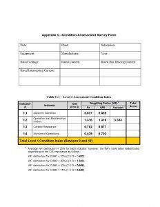
Enter the CIS scores from Table 1 to 4, as appropriate, into the CA Survey Form in Appendix C Table C.1. Multiply each CIS by the Weighting Factor (WF), and sum the Total Scores to arrive at the Level 1 CI. The CI may be adjusted by the Level 2 inspections, tests, and measurements described below. Suggested alternatives for follow up action, based on the CI, are described in the Condition-Based Alternatives at Appendix D in Table D.1.
7. Level 2 Inspections, Tests, and Measurements of Switchgear and Controlgear
Level 2 inspections, tests, and measurements generally require specialized equipment or training, may be intrusive, or may require an extended outage to perform. Level 2 assessments is considered non-routine. Level 2 inspections are intended to affect the Condition Index number established using Level 1, but also may confirm or refute the need for more extensive maintenance, rehabilitation, or circuit breaker replacement.
Presently, there are only two Level 2 tests: interrupter inspection and a comparison of available short circuit current with the breaker’s interrupting rating. However, emerging technologies, such as partial discharge and acoustic emissions, are being explored for potential use.
The comparison of the available short circuit currents and the breaker’s interrupting rating requires expert analyses and up-to-date short circuit studies. Because of the importance of the results of the comparison, the adjustment to the Condition Index for poor comparison results is significant.
For Level 2 assessments performed, apply only the appropriate adjustment factors per the instructions above and recalculate the Condition Index using the Condition Assessment Summary at Appendix B.
A circuit breaker or fused contactor cannot be safely returned to service with unresolved deficiencies in the internal mechanisms that affect its performance. If the problems found can be repaired, the device should be repaired and the appropriate Level I tests repeated.
It may be appropriate to lower the O&M History indicator score based on the findings of the interrupter inspection and repair. For each Level 2 inspection, test, or measurement performed, subtract the appropriate amount from the appropriate Level 1 condition indicator and recalculate the CI using the CA Survey Form in Appendix C Table C.2.
Test 1: Interrupter Inspection
Performing an inspection of an interrupter requires a significant outage of the circuit. The decision to perform an interrupter inspection would most likely be based on finding problems with the breaker’s timing and travel adjustments or with excessive contact resistance. An interrupter inspection would include disassembly of the breaker or contactor and inspection of all moving and stationary internal components. Results are analyzed and applied to Table 5 to arrive at a CI score adjustment.
Table 5 – Interrupter Inspection Scoring

A circuit breaker or contactor cannot be safely returned to service with unresolved deficiencies in the internal mechanisms that affect its performance. If the problems found can be repaired, the breaker should be repaired and the appropriate Level I tests repeated. It may be appropriate to lower the O&M History indicator score based on the findings of the interrupter inspection and repair.
Test 2: Circuit Breaker Ratings vs. Available System Fault Current
Circuit breakers are chosen such that interrupting current ratings exceed the maximum available fault current. There is also an allowance provided for the system fault contribution to grow with time included in the calculations. Operating a circuit breaker under conditions exceeding the ratings of the breaker can result in failure of the breaker and considerable incidental damage to adjacent equipment.
It is prudent to periodically review the adequacy of the bus and circuit breaker’s ratings compared with the system growth. Therefore, the first step in assessing the condition of a circuit breaker should be comparing the interrupting current rating of the breaker with the present and projected system fault current that the breaker must be capable of interrupting. This will require an up-to-date system fault study to provide the new and projected system contributions. CSD should be consulted when comparing the breaker ratings with the projected system fault currents.
Table 6 – Level 2 Current Interrupting Rating Scoring

Test 3: Other Specialized Diagnostic Tests
Utilize additional tests that may be applied to evaluate specific circuit breaker problems. Some of these diagnostic tests may be considered to be of an investigative research nature. When conclusive results from other diagnostic tests are available, they may be used to make an appropriate adjustment to the Condition Index. These tests include partial discharge testing, light based detection, ultrasound and gas detection based techniques.
Level 2 Switchgear Condition Index (CI) Calculations
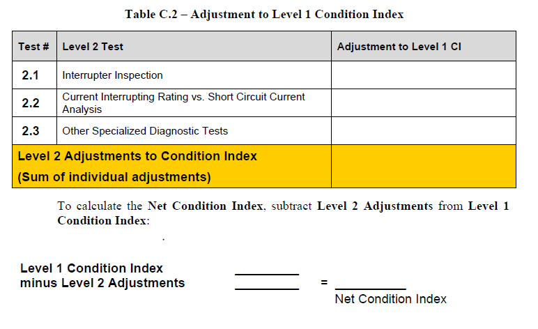
Enter the Level 2 adjustments from the tables above into the CA Survey Form in Appendix C Table C.2. Subtract the sum of these adjustments from the Level 1 CBCI to arrive at the total CI index.
Suggested alternatives for follow up action are described in the Condition-Based Alternatives in Appendix D.
Appendix A – Switchgear Condition Assessment Methodology
Appendix B – Switchgear Condition Assessment Summary
Appendix C –Condition Assessment Survey Form
Appendix D – Switchgear and Controlgear Condition-Based Alternatives

Appendix E – Switchgear and Controlgear Inspection Checklist (Please Click Here. Switchgear and Controlgear Inspection Checklist )