- Introduction
- References
- Definitions and Abbreviations
- Motor Pre-FAT Tests
- Motor Factory Acceptance Tests
- FAT Checklist
Synchronous Motor Factory Acceptance Test – Motor FAT Procedure
1. Introduction Motor FAT Procedure
1.1 Purpose
The purpose of this procedure is to provide guidance to the Project Engineer, Proponent or Inspection Engineer participating in the Factory Acceptance Test (FAT) of a large synchronous motor.
1.2 Scope
This article is developed to provide guidance on the tests conducted on the motor throughout its construction, as well as the final tests conducted during the FAT. The ultimate objective is to be aware of the tests that are to be conducted during the FAT, and to clarify the criteria for motor final acceptance.
2. References Motor FAT Procedure
This Article is based on the latest edition of the references below:
Industry Codes and Standards
American Petroleum Institute (API)
API STD 546 Brushless Synchronous Machines (2nd Edition) International Electrotechnical Commission (IEC). IEC 34 Rotating Electrical Machines (Series) International of Electrical and Electronics Engineers (IEEE).
IEEE 43 Recommended Practice for Testing Insulation Resistance of Rotating Machinery.
IEEE 62.2 Guide for Diagnostic Field Testing of Electric Power Apparatus.
IEEE 115 – 1995 Test Procedures for Synchronous Machines.
IEEE 286 Practice for Measurement of Power Factor Tip-Up of Electric Machinery Stator Coil Insulation.
IEEE 522 Guide for Testing Turn Insulation of Form-Wound Stator Coils for AC Electric Machines.
IEEE 1434 Guide to the Measurement of Partial Discharges in Rotating Machinery International Organization for Standardization.
ISO 3744 Acoustics – Determination of Sound Power Levels of Noise Sources Using Sound Pressure.
National Electrical Manufacturers Association (NEMA)
ANSI/NEMA MG 1 Motor and Generators
3. Definitions and Abbreviations
Complete Test: A test made to determine the adequacy of the design of a particular type, style, or model of equipment and its component parts to meet its assigned ratings and to operate satisfactorily under normal service conditions or under special conditions if specified; and to demonstrate compliance with appropriate industry standards.
Factory Acceptance Test (FAT): A performance running test conducted at the factory to check the integrity of the equipment.
Hot Spot: A hot spot is defined as an area where the stabilized temperature is more than 5°C higher than the surrounding average.
Inspection and Test Plan (ITP): A pre-approved document that guides manufacturer of the tests that are required, and the level of witnessing/review associated with each test.
Routine Test: A test to verify the quality control of the manufacturer which is performed on all equipment. This test ensures the quality and uniformity of the workmanship and materials used. Routine tests are sometimes referred to as production tests.
Stable Temperature: Temperature is considered stable when it changes by less than 1°C in 30 minutes.
4. Motor Pre-FAT Tests
The following tests should have been conducted throughout the construction process of the motor. Most of these tests have either been witnessed or their documents reviewed earlier and approved, as agreed in the ITP and Inspection Requirements. A review of these documents, at the time of the FAT, is an added quality
check.
4.1 Stator Core Test (17-SAMSS-520 / para. 4.3.4.1)
This test is designed to evaluate the quality of the stacked core and the insulation between the core laminations. Current is injected through cable loops placed around the stator core (not inside the slots), inducing flux densities simulating a real machine, usually in the range of 1 to 1.5 Tesla, as per IEEE 62.2, section 7.2. The test is conducted for a minimum of 30 minutes to allow for a rise in core temperature.
The search for any hot spots, 5°C above the surroundings, should be conducted using an infrared camera.
4.2 Surge Comparison Test (17-SAMSS-520 / para. 4.3.4.2)
Also known as the impulse test, it is designed to detect main insulation and inter-turn insulation integrity of the stator windings. This test is a comparative one, and a change in the wave form indicates a short circuit between turns. Test details and voltage levels and rise time specific values are clear in IEEE 522,
section 6 or IEC 34-15.
4.2.1. Test of main insulation is conducted by applying three successive voltage impulses of 5 pu voltage.
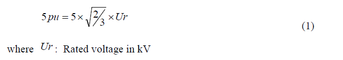
4.2.2. Test of inter-turn insulation consists of successive voltage impulses of 2.0, 3.5 and 5 pu, with a rise time of 0.1 to 0.2 μs.
4.3 Power Factor Tip-Up Test (17-SAMSS-520 / para. 4.3.4.3)
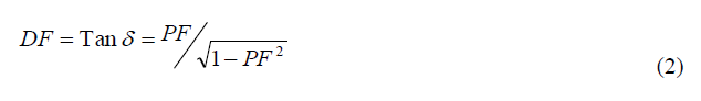
Also known as the Dissipation Factor (DF) as well as tan-delta (Tan δ), this test reflects the density of voids in the stator winding insulation, and the existence of the corona or slot partial discharge (PD). PD consumes energy as it occurs, and its occurrence increases with higher voltages, thus, this test identifies the amount of PD activity by measuring the energy it consumes.
The test results are presented in the form of a curve of the power factor as a function of the line-to-ground voltage. A fast change in the power factor tends to indicate a coil with many voids.
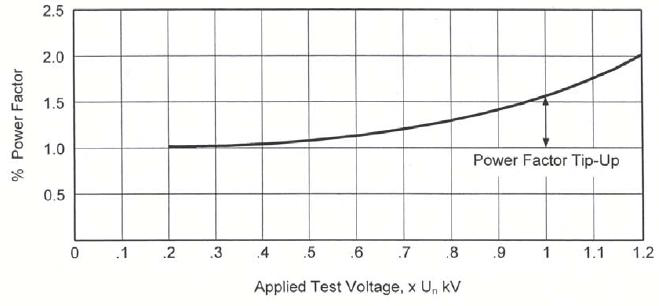
The test is done at 25% and 100% of rated line-to-ground voltage, and the tip-up is the PF in % at the higher voltage minus that at the lower voltage, and should not exceed 1% otherwise, the results should be reviewed and evaluated (IEEE 286 or IEC 34-29).
4.4 Sealed Winding Conformance Test (17-SAMSS-520 / para. 4.3.4.4)
The test can be accomplished by two methods, first submerging the complete stator in a water tank, and the second by spraying the windings with water for 30 minutes. In both cases, the water must consist of a wetting agent. Practically all manufacturers use the second method. The test is detailed in NEMA MG 1,
section 20.18, and consists of the following steps:
4.4.1. Test the winding insulation with 500V DC for 10 minutes, correct the values to 40°C, and compare to acceptable limits in IEEE 43.
4.4.2. Conduct a Hi-pot test at 1.15 rated line to line rms voltage for 1 minute.
4.4.3. Repeat the test of 4.4.1, for 1 minute.
4.5 Partial Discharge
This test is conducted on each phase of the stator winding, as it measures the high frequency current discharge pulses, resulting due to voids in the insulation and corona. The readings are usually taken through a capacitive link between the winding and measurement equipment. Alternatives include the use of a corona camera probe, ultrasonic probe, blackout or ultraviolet imaging, and most recently online PD measurement. The use of online PD monitoring is increasing, as it can assist in avoiding sudden failure and unplanned outages.
As a minimum, Partial Discharge Inception Voltage (PDIV) and Partial Discharge Extinction Voltage (PDEV) shall be recorded for each phase as well as power supply frequency, temperature and humidity at the time of test. The acceptance criteria shall be mutually agreed upon between the vendor and purchaser prior to performing the tests (IEEE 1434/para. 10.2 or IEC 34-27).
4.6 Probe-Track Run-out and Rotor Balancing
4.6.1. The probe track run-out should have been obtained with the shaft supported on v-blocks, and the readings not exceeding 13 micrometers (17-SAMSS-520 / para. 2.4.5.1.7a).
4.6.2. Rotor final balancing in a balancing machine shall not exceed pre-defined limits for residual unbalance in the correction plane (API STD 546 / para. 2.4.6.3).
4.7 Current-Time Characteristics
The current-time characteristics diagram represents the stator current Vs time at 80%, 100% and usually at 110% of rated voltage. Current-time characteristics will be presented similar to the figure.
4.8 Hot/Cold damage limits
The hot and cold damage limits must be provided. This will also include the allowable number of motor starts from cold and again from hot.
4.9 Differential Self Balancing Protection CT Test
The differential self balancing CT (50:5 class C20 or higher for each phase) test is performed to determine the CT accuracy and performance. Furthermore, magnetization curve shall be obtained through 13 test points.
4.10 Winding and Bearing Resistance temperature detectors (RTDs) Tests
RTDs provided for monitoring stator temperature shall be verified 100-ohm, platinum, three lead type with a temperature coefficient of resistance equal to 0.00385 ohm/ohm/°C.
4.11 Excitation Control Panel
The excitation control system should have been tested separately, and must consist of the following protection:
Out of step
Field current failure
Field overcurrent
Under excitation
Diode failure
It must also be microprocessor based and consist of manual and automatic excitation control operations, while the automatic shall consist of three modes; VAR Control, PF Control, and AVR Control.
4.12 Capability Diagram
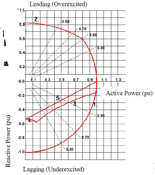
The capability diagram represents the rotor and stator thermal and stability limits, and will most likely have been determined during the motor design stage. The limits will be represented in a graphical format, similar to the figure. The motor limits are represented as follows:
1. Stator heating limit
2. Rotor heating limit
3. Practical stability limit
4. Zero field current limit
5. Core end heating limit
5. Motor Factory Acceptance Tests
5.1 Routine Test
The main goal of conducting the routine test is to insure that the motor is free from electrical and mechanical defects. Therefore, each machine shall undergo the routine test, which consists of the following procedures, per API STD 546, while additional guidelines for these tests can be obtained from NEMA MG 1 and IEEE 115, or IEC 34-2 and IEC 34-4:
5.1.1. Measure the no-load current, on each phase, and the exciter field current if applicable.
5.1.2 Record and plot the locked-rotor current.
5.1.3 Conduct the high-potential test on the stator windings, space heaters, and RTDs.
The Hi-pot test objective is to test for major flaws in the winding insulation, as this high voltage would cause insulation breakdown at the defect. It is considered a potentially-destructive test, and the result is a pass/not pass motor. Caution must be taken into consideration and assurance of the correct voltage is applied for the required one minute.
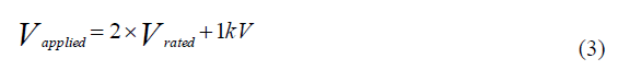
An equivalent DC test is possible with prior approval, but the AC test is more indicative of the machine condition, and the applied voltage shall be as follows:
5.1.4 Perform an insulation resistance (IR) test and polarization index (PI).
IR test is performed on the stator and rotor windings, terminal box connections, and all auxiliaries using a mega-ohm-meter device to measure the resistance value between the conductors in different phases,
as well as between conductors and ground. As DC voltage is applied, there are four different types of currents that may flow indicating the condition of the insulation; capacitive, conduction, surface leakage, and absorption currents.
For the IR test, the windings are subjected to a DC voltage, per Table 6 of API STD 546, for 1 minute. The readings are sensitive to temperature, and thus, the values are corrected to 40°C, and then compared to the acceptable limit of 100 mega-ohm. (IEEE 43).
PI is the ratio between the IR readings at 10 minutes and at 1 minute. This test is used to measure the degree of dryness and cleanliness of a winding. The minimum PI measured values must be higher than 2 for Class B and F insulation. But for new windings, a minimum of 3 is expected.
The PI test is usually conducted before a Hi-Pot test, to make sure that the winding is dry to avoid unnecessary damage to the windings, and again after the hi-pot to insure winding integrity.
5.1.5 Measure stator winding resistance.
A digital low resistance meter that uses DC voltage should be used. The resistance value of the winding is measured at room temperature between the winding terminals, or if the star connection is not open, between each two phases. Large machines have relatively low resistance values, so readings must consist of at least 3 decimal places for accuracy and comparison. The test is performed on stator and rotor windings, and the variance between phases/poles should not exceed 1%.
5.1.6 Measure vibration.
Vibration testing and measurement guide is available in the Dynamic Analysis Best Practice (SABP-G-005), with reference to 17-SAMSS-520 para 2.4.6.4.1, NEMA MG 1 and IEC 34-14.
5.1.7 Measure bearing insulation resistance.
Check the resistance measurement across the bearing to verify bearing insulation integrity. A megaohm-meter should be used.
5.1.8 Monitor bearing temperature rise.
The motor shall be operated at no load for at least 1 hour after the bearing temperatures have stabilized. This is to verify bearing integrity.
5.1.9 Inspect the bearings and oil supply, if applicable.
Following the running test, the sleeve bearings top and bottom halves must be completely removed and the shaft journals and bearings must be inspected. A minimum of 80% surface contact shall be evident between the shaft journal and the bearing bore, with no edge loading. If the lubricant can be accessed, its condition should be examined for search of discoloration of availability of particles, following the run test.
5.1.10 Measure machine air gap and exciter air gap.
Air gap must be measured from at least three different positions, and at identical positions on both sides of the rotor. The most ideal measurement locations are at the 3, 6, 9, and 12 o’clock positions. Percent variation shall not exceed 10% (API STD 546 / para. 2.4.7.2.4)
5.1.11 Measure shaft voltage and current.
Unbalance in the magnetic circuits, or in the winding phase currents, can create additional flux linkages that can interact with the shaft and produce a potential difference between both sides of the shaft. This
could develop a circulating current if the bearings are not insulated or a high voltage buildup on the shaft when both bearings are insulated. Therefore, shaft voltage measurement is required to insure no
deficiencies in the motor. (IEEE 115 / para. 3.6).
5.2 Complete Test
Unless otherwise specified, a complete test is required on a single motor (or one of a series of motors with identical design) to insure the correct design and performance of this specific design. This is applicable for all motors rated 6.6 kV and above and all motors rated above 3700 kW (5000 HP). This test consists of
the following procedures, per API STD 546, while additional guidelines for these tests can be obtained from NEMA MG 1 and IEEE 115, or IEC 34-2:
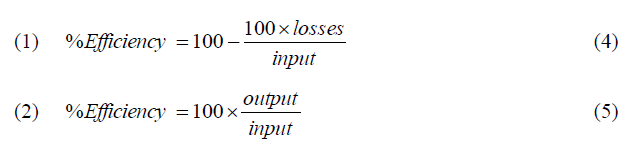
5.2.1 Verify efficiency at 100%, 75%, and 50% of full load.
The determination will be performed by one of the methods described in IEEE 115, section 4.6, whether by segregating the losses, as in (1) or identifying input and output, as in (2). Losses are usually determined by
conducting an open-circuit test as well as a short-circuit test. IEC 34-2 calculation methods are also acceptable.
5.2.2 Determine the locked-rotor current, torque and power factor.
The rotor is mechanically locked to record power measurement readings at the locked rotor position. Applying full voltage may not always bepractical. Test procedure is detailed in IEEE 115, section 7.2.
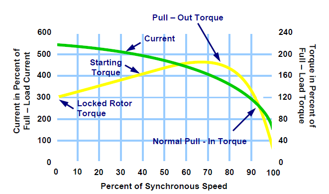
5.2.3 Determine the pullout and full load torque and current values.
Locked rotor and pullout values are detailed in IEEE 115, section 7.4. Details of the four different methods in developing the torque-speed curve are mentioned in IEEE 115, section 7.3, which will be selected by
the vendor. A sample of a torque-speed curve is shown below. Torque must be 10% larger than the anticipated load curve, to insure motor proper startup and avoiding a stall.
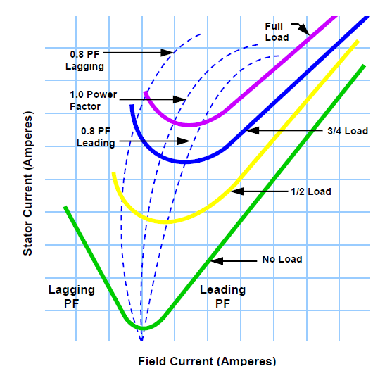
5.2.4 Determine the actual speed-torque and no-load V curves. These figures are plotted based on results and calculations using data from the open circuit and short circuit tests.
5.2.5 Measure the noise attenuation of the motor.
This test is described in SABP-G-005. During the test, the motor shall be operating at no load, full voltage, rated frequency, and sinusoidal power, and the measurement shall be per NEMA MG 1 or ISO 3744. 5.2.6 Measurement of losses.
Losses consist of stator and rotor copper (I2R) losses, iron core losses, stray-load losses, and friction and windage losses. The no-load, open-circuit saturation, and short-circuit saturation tests are all used to calculate these machine losses. (IEEE 115 or IEC 34-2/4)
5.3 Heat-Run Test
Unless otherwise specified, a heat run test (also known as the temperature rise test) is required on a single motor (or one of a series of motors of identical design) to insure the correct design and performance of this specific design.
5.3.1 This test is intended to monitor several parameters and track their rate of change over the complete test. These parameters include the following:
Stator winding temperature
Exciter temperatures
Bearing temperature
Lube oil temperature (must be preheated if used from a common oil system)
Cooling air inlet/outlet temperature (if applicable)
Cooling water inlet/outlet temperature and flow (if applicable)
Vibration; vibration readings must fall within acceptable limits when the motor is unloaded, while readings throughout the run test are for trending.
5.3.2 The heat run must be conducted at full load, for four hours or until the bearing and stator winding temperatures stabilize.
The test must comply with one of the procedures of IEC 34-29, or IEEE 115, section 6, which specifies different methods of loading the motor.
5.3.2.1 Actual loading method: The machine is mechanically coupled and loaded. This would normally be the simplest option, but is uncommon since it is limited in size. Also, maintaining terminal voltage is normally an issue.
5.3.2.2 Synchronous feedback:
Where two similar synchronous machines are connected back to back, one as a motor and the other as a generator, with the generator supplying the motor.
The losses are compensated by a third motor supplied externally.
5.3.2.3 Zero power factor:
The machine is operated uncoupled, as a synchronous condenser, running at rated current, voltage and frequency.
5.3.3 The stator winding resistance is measured while the stator is hot, as soon as possible following switching off the motor. The value decreases as the winding cools down, therefore, the reading is extrapolated to the instant the motor was switched off.
FAT Ckecklist
| Test | Acceptable | Not Acceptable | Notes |
Pre-FAT Tests |
| Stator Core | |||
| Surge Comparison | |||
| Power Factor Tip-Up | |||
| Sealed Winding Conformance | |||
| Partial Discharge | |||
| Probe-Track Runout | |||
| Rotor Balancing | |||
| Excitation System | |||
| Diff. Self Balance CT Test | |||
| Winding & Bearing RTD Test |
FAT Tests |
| No-load current | |||
| High-potential | |||
| Insulation resistance (IR) | |||
| Polarization index (PI) | |||
| Stator winding resistance | |||
| Vibration | |||
| Bearing insulation resistance | |||
| Bearing temperature rise | |||
| Inspection of bearings and oil supply | |||
| Machine air gap |
| Shaft voltage | |||
| Efficiency at 100%, 75%, and 50% of full load | |||
| Locked-rotor current, torque and power factor | |||
| Pullout torque | |||
| Speed-torque curve | |||
| No-load V-curve | |||
| Noise attenuation | |||
| Losses |
Heat-Run Test |
| Stator winding temperature | |||
| Exciter temperatures | |||
| Bearing temperature | |||
| Lube oil temperature | |||
| Cooling air inlet/outlet temp | |||
| Cooling water inlet/outlet temp and flow (if applicable) | |||
| Vibration |
More about Motor SYNCHRONOUS MOTOR ELECTRICAL DESIGN.